In this tutorial, we are going to look at thermistors and their interfacing with Arduino. A thermistor is an electronic device that exhibits a change in electrical current based on the variation in temperature. The name thermistor is a combination of “thermal” and “resistor”, so a thermistor is a sensitive resistor whose resistance varies with temperature changes. Nowadays, thermistors are used in many projects where temperature monitoring is necessary due to their small size, accuracy, and fast response times.
Recommended Components
The following components are used in this project or are helpful for building it with the Arduino.
| Component | How it’s used in this project | Buy on Amazon |
|---|---|---|
| Arduino Uno R3 | The main microcontroller board that runs the project code and controls all connected components. | Check Price |
| Thermistor Module | Senses ambient temperature and feeds an analog value to the Arduino to build the temperature meter. | Check Price |
| Breadboard | Lets you build and prototype the circuit without soldering. | Check Price |
| Jumper Wires | Used to make the connections between the Arduino, breadboard and the modules. | Check Price |
As an Amazon Associate we earn from qualifying purchases. Prices and availability are accurate as of the date/time indicated and are subject to change.
Types of Thermistors
There are two main types of thermistors, these are listed in the table below:
| Type of Thermistor | Function of Thermistor |
| Positive Temperature Coefficient (PTC) | The PTC thermistors resistance increases as the temperature increases. |
| Negative Temperature Coefficient (NTC) | The NTC thermistors resistance decreases as the temperature increases. |
Note: A Negative Temperature Coefficient (NTC) is the most common type of thermistor used in projects and applications.
YouTube Video
Thermistor Module
The thermistor module (KY-028) is useful for measuring the temperature. It gives output on both the analog and digital pins. This module has three components: a thermistor, a 100 k ohm potentiometer, and a LM393 comparator. We have explained each of these below:
- Thermistor: Thermistor is a very cheap, inexpensive, and accurate sensor. It is like a variable resistor whose resistance changes with the change in temperature.
- 100k ohm Potentiometer: It is basically used for the digital output. The digital output can be changed by changing the value of the potentiometer.
- LM393 comparator: The LM393 comparator compares the values of the thermistor and the potentiometer to give a digital output.
This KY-028 module has the capability of producing both analog and digital output. The analog voltage will provide a varying value based on the temperature. Whereas the digital pin provides us with a logic set of 0 or 1 based on the potentiometer.
How Thermistor Module Works?
The value of the thermistor changes with the change in temperature. A 100k ohm variable resistor is connected in series with the thermistor across 5V and ground. The center pin of the potentiometer has a voltage that changes with temperature. The Arduino can measure the analog output A0 of this module using the analog pins. For the digital output, an LM393 comparator will compare the voltage from the thermistor and the potentiometer to give an output in logic 1 or 0 at the D0 pin.
Specifications
The specifications of thermistor module are provided below:
- The operating voltage of this module is between 3.3V and 5V.
- The functional temperature measurement range is between -55°C and 125°C [-67°F and 257°F].
- This module has an accuracy of ±0.5°C.
- The board dimensions of KY-028 are 15mm x 36mm [0.6in x 1.4in].
Pinout of Thermistor Module

The KY-028 module has four pins, we will explain these pins in the table below:
| Thermistor Module Pin | Function of the Pin |
|---|---|
| A0 | This pin provides analog output. |
| D0 | The D0 pin is for digital output. |
| GND | This is the Ground pin of the KY-028 module. |
| 5V | This pin provides the power to the KY-028 module. |
Hardware Components
Here we have listed the hardware components we will be using in this tutorial:
- Arduino UNO board
- KY-028 thermistor module
- Jumper Wires
Thermistor Interfacing with Arduino Schematic Diagram
In this section, we have provided the schematic diagram. This schematic diagram helps us properly connect our Arduino Board to the KY-028 thermistor module.
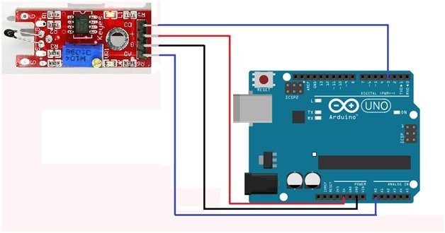
The wiring schematic is very simple. We have connected the GND pin of the KY-028 Thermistor Module to the GND pin of our Arduino Board. Then we connected the 5V pin to the 5V of the Arduino board. At the last step, we connected the D0 and A0 pins of the thermistor module to pins 3 and A0 of the Arduino board. These connections can be seen in the schematic above.
Note: In case we require a set point for digital output, we need to move the potentiometer’s screw using a screwdriver. If the LED is off, we will move the screw clockwise until the LED is on. After the LED turns on, we will move the screw in an anticlockwise direction until the LED goes off. In this way, we can test the digital output of the LED.
Arduino Sketch – Thermistor Module
Open the Arduino IDE and go to File > New to create a new file. Now copy this sketch given below and paste it in the Arduino File. Select the COM port of the connected Arduino board and click Upload. This will upload the sketch to the Arduino board. This sketch includes comments for the clear understanding and working of each line.
// This code is for the Analog and digital temperature sensor module

#define LED_PIN 13                            // defining pin 13 as the led input pin

#define DIGITAL_INPUT 3                   // defining digital input at pin 3

#define ANALOG_INPUT   A0            // defining analog input at A0

// initializing the variables

int    digital_output ;                          // This will read the digital value

int    analog_output ;                        // This will read the analog value

int    revised_output;                        // variable to store the corrected value

float  temp_C ;                                  // Variable for storing the temperature

float  temp_f ;                                  // Variable for storing the Fahrenheit

void setup ( )                                                                       // Anything written I it will run once.

{

  pinMode ( LED_PIN, OUTPUT ) ;                               // declaring pin 13 as output

  pinMode ( DIGITAL_INPUT, INPUT ) ;                   // declaring pin 3 as input

  pinMode ( ANALOG_INPUT, INPUT )  ;                 // declaring A0 as input pin

  Serial.begin ( 9600 ) ;                                            // selecting the baud rate at 9600

  Serial.println (" microcontrollerslab.com : The data is " ) ;

}

void loop ( )                               // Anything written in it will run continuously

{

  analog_output = analogRead ( ANALOG_INPUT ) ;         // Reading the analog value and storing in analog_output

  Serial.print ( " Analog value of the module is =  " ) ;

  Serial.print ( analog_output ) ,  DEC ;                                    // This will display the analog value


  // The module has thermistor connection reversed

 revised_output= map ( analog_output, 0, 1023, 1023, 0 ) ;


  temp_C    = Thermistor ( revised_output ) ;

  temp_f = ( temp_C * 9.0 ) / 5.0 + 32.0 ;


// Reading the digital data

  digital_output = digitalRead ( DIGITAL_INPUT ) ;

  Serial.print ( "   Digital value of the module is =  " ) ;

  Serial.println ( digital_output ) , DEC ;     // This will display the digital value on the display

  Serial.print ( " LED is =" ) ;

  if ( digital_output == HIGH )   // The LED will turn on When the sensor value will exceed the set point

  {

    digitalWrite ( LED_PIN, HIGH ) ;

    Serial.print ( "ON " ) ;

  }

  else

  {

    digitalWrite ( LED_PIN, LOW ) ;

    Serial.print ( "OFF " ) ;

  }

// This will print the temperature

  Serial.print ( " Measured Temperature = " ) ;

  Serial.print ( temp_f, 1 ) ;    // This will display the temperature in Fahrenheit

  Serial.print (" F  " ) ;

  Serial.print  (temp_C, 1 ) ;  // This will display the temperature in Celcius

  Serial.println (" C " ) ;

  Serial.println ( ) ;     // Leaving a blank line

  Delay ( 1000 ) ;       // Wait for 1 second

}

double Thermistor ( int RawADC )

{

double Temp ;

  Temp = log ( ( ( 10240000 / RawADC ) – 10000 ) ) ;

  Temp = 1 / ( 0.001129148 + ( 0.000234125 * Temp ) + ( 0.0000000876741 * Temp * Temp * Temp ) ) ;

  Temp = Temp - 273.15 ;     // This will Convert Kelvin to Celsius

  return Temp ;

}
Sketch Explanation
In this section, we will explain the working of this sketch.
#define LED_PIN 13           // defining pin 13 as the led input pin

#define DIGITAL_INPUT 3       // defining digital input at pin 3

#define ANALOG_INPUT   A0    // defining analog input at A0
In the first few lines, we have defined three pins. LED pin as pin 13, Digital pin as pin 3, and Analog pin as pin A0 of the Arduino board.
int    digital_output ;      // This will read the digital value

int    analog_output ;     // This will read the analog value

int    revised_output;    // variable to store the corrected value

float  temp_C ;      // Variable for storing the temperature

float  temp_f ;       // Variable for storing the fahrenheit
Then we initialized a few variables. These variables are for storing outputs and temperature values in both the Celsius and Fahrenheit scales.
void setup ( )          // Anything written I it will run once.

{

  pinMode ( LED_PIN, OUTPUT ) ;      // declaring pin 13 as output

  pinMode ( DIGITAL_INPUT, INPUT ) ;     // declaring pin 3 as input

  pinMode ( ANALOG_INPUT, INPUT )  ;   // declaring A0 as input pin

  Serial.begin ( 9600 ) ;      // selecting the baud rate at 9600

  Serial.println (" microcontrollerslab.com : The data is " ) ;

}
In the void setup function, we have set the pin modes of each pin. These modes are set using the pinMode() function. Afterward, we started the serial monitor at a baud rate of 9600. Then we printed a statement on the serial monitor.
void loop ( )      // Anything written in it will run continuously

{

  analog_output = analogRead ( ANALOG_INPUT ) ;   // Reading the analog value and storing in analog_output

  Serial.print ( " Analog value of the module is =  " ) ;

  Serial.print ( analog_output ) ,  DEC ;     // This will display the analog value


  // The module has thermistor connection reversed

 revised_output= map ( analog_output, 0, 1023, 1023, 0 ) ;


  temp_C    = Thermistor ( revised_output ) ;

  temp_f = ( temp_C * 9.0 ) / 5.0 + 32.0 ;
In the void loop function, we read the analog input from the thermistor module at pin A0. Here, we calculate the temperature in Celsius and Fahrenheit using the revised output variable.
// Reading the digital data

  digital_output = digitalRead ( DIGITAL_INPUT ) ;

  Serial.print ( "   Digital value of the module is =  " ) ;

  Serial.println ( digital_output ) , DEC ;    // This will display the digital value on the display

  Serial.print ( " LED is =" ) ;

  if ( digital_output == HIGH )   // The LED will turn on When the sensor value will exceed the set point

  {

    digitalWrite ( LED_PIN, HIGH ) ;

    Serial.print ( "ON " ) ;

  }

  else

  {

    digitalWrite ( LED_PIN, LOW ) ;

    Serial.print ( "OFF " ) ;

  }

// This will print the temperature

  Serial.print ( " Measured Temperature = " ) ;

  Serial.print ( temp_f, 1 ) ;    // This will display the temperature in Fahrenheit

  Serial.print (" F  " ) ;

  Serial.print  (temp_C, 1 ) ;   // This will display the temperature in Celcius

  Serial.println (" C " ) ;

  Serial.println ( ) ;     // Leaving a blank line

  Delay ( 1000 ) ;       // Wait for 1 second

}
Then, using the Digital pin input at pin 3 of the Arduino board, We will control the Built-in LED of the Arduino board. Afterwards, using the variables, we will print the temperatures on the serial monitor.
double Thermistor ( int RawADC )

{

double Temp ;

  Temp = log ( ( ( 10240000 / RawADC ) – 10000 ) ) ;

  Temp = 1 / ( 0.001129148 + ( 0.000234125 * Temp ) + ( 0.0000000876741 * Temp * Temp * Temp ) ) ;

  Temp = Temp - 273.15 ;    // This will Convert Kelvin to Celsius

  return Temp ;

}
In this last part, we will use the temp variable to calculate the temperature on the Kelvin scale.
Output of Sketch
The output of this sketch is as follows:
microcontrollerslab.com : The data is

Analog value of the module is = 768   Digital value of the module is = 1

LED is = OFF Measured Temperature = 80.2 F 19.3 C
Conclusion
Here we have summarized the things we have learned in this article:
- Thermistors and their types.
- Thermistor Module and its functions.
- Pinout and Schematic diagram of the thermistor module.
- Sketch, example, and output.
Related Articles:
In case you want to read a similar article, please check out the following link
Other Arduino tutorials:
- Interface HTU21D Temperature & Humidity Sensor with Arduino
- TCA9548A I2C Multiplexer Arduino Use Same Address I2C Devices
- Interface MS5611 Barometric Pressure Sensor with Arduino
- MPU9250 9-DOF Gyro Accelerator Magnetometer Module with Arduino
- Interface SHT31 Temperature & Humidity Sensor with Arduino
I hope that you have gained useful knowledge after reading this article. Let us know in your comments if you have any issues.
Delay should read delay
Hi,
I bought this (https://robu.in/product/4pin-ntc-thermistor-temperature-sensor-module/ ) thermistor. Im new to arduino. i directly connected GND, A0 and VCC to arduino (without any resister).
I followed your code and got analog value in the range of 550 (connected to 3.3v supply). But the temperature is coming as ~21C.
Is this correct? To me, it looks less than what it is supposed to be (as the room feels warmer than 21C).
can you please help?
Thanks,
Pragalathan M
Note: When i change to 5v supply, the reading is ~830 and goes to -5.7C.