In this user guide, we will learn to interface SHT31 Temperature and Humidity Sensor module with Arduino. Firstly, we will introduce you to SHT31 sensor including its pinout, features, and interfacing with Arduino. Secondly, we will install the Adafruit SHT31 library in Arduino IDE to access the sensor data. Lastly, we see two examples to display temperature and humidity values on a serial monitor and on the SSD1306 OLED display.
We have a similar guide with ESP32:
Recommended Components
The following components are used in this project or are helpful for building it with the Arduino.
| Component | How it’s used in this project | Buy on Amazon |
|---|---|---|
| Arduino Uno R3 | The main controller board that runs the sketch, reads the SHT31 over I2C, and drives the OLED. | Check Price |
| Breadboard | Solderless board to mount the SHT31 and OLED and wire them to the Arduino. | Check Price |
| Jumper Wires | Connect the Arduino A4/A5 I2C lines, 5V, and GND to the SHT31 and OLED. | Check Price |
| SHT31 Temperature & Humidity Sensor | The I2C sensor this project reads, providing the temperature and humidity values. | Check Price |
| 0.96″ SSD1306 OLED Display | Shows the live SHT31 temperature and humidity readings in the second example. | Check Price |
As an Amazon Associate we earn from qualifying purchases. Prices and availability are accurate as of the date/time indicated and are subject to change.
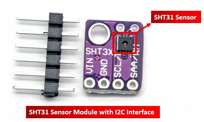
SHT31 Sensor Module Introduction
The SHT31 temperature and sensor module comes in a compact user-friendly size that features the SHT31 chip from Sensirion. This chip is in fact the temperature and humidity sensor that offers various functions, interfaces and extremely easy to use with a microcontroller. The sensor is able to measure temperature readings in the range of -40 to 125°C with a good accuracy of ±0.2°C. Similarly, the SHT32 chip also offers a humidity sensor which offers an operating humidity range of 0-100% with a typical relative humidity accuracy of 2%.
Due to its small size, low cost, and wide operating voltage range of 2.15-5.5V, the SHT31 sensor is a great choice to be used with microcontrollers for temperature and humidity measurements e.g. thermostats, weather stations, etc.
I2C Interface
The SHT31 Sensor Module uses I2C communication protocol to transmit sensor data to the microcontroller. The sensor module features the SCL (serial clock) and SDA (serial data) pins which connect with the I2C interface of Arduino or other sensors supporting the same interface.
One interesting thing to note here is that, the SHT31 sensor module comes with two I2C addresses which are 0x44 and 0x45. By default, the I2C address is set as 0x44. The user can change the I2C address through the I2C Address Selection Pin commonly known as AD.

The AD pin consists of an internal pull-down resistor which ensures that when this pin is unconnected (low state), the I2C address is 0x44 (default). Whereas, when the state of this pin is set high then the I2C address is 0x45. This address changing feature gives the users the liberty to use multiple SHT31 sensor modules on the same bus by setting the same I2C address for each sensor.
Alert Output Pin
The SHT31 sensor module has a unique feature that it features an alert output pin commonly known as AL to set the module in Alert Mode. By using this pin, the user can enable the sensor to work alongside the microcontroller where the sensor keeps on obtaining readings and the microcontroller works on different tasks. This happens whenever the temperature and humidity readings are greater than the user defined range. The AL pin therefore acts as a triggering pin that works like an interrupt.
The AL pin goes to a high state whenever either of the humidity or temperature reading crosses the upper or lower user defined limit. The pin remains in the high state until the values go back to the normal limit range.

SHT31 Sensor Module Pinout
The following figure shows the pinout diagram of SHT31 sensor module. SHT31 sensor module consists of six pins.
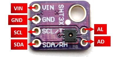
The following lists the pinout of the SHT31 sensor module and their brief description.
| SHT31 Module Pin | Description |
|---|---|
| VIN | This is the pin that supplies power to the sensor module in the range 2.4-5.5V. Connect it with 5V pin of Arduino. |
| GND | This is the ground pin for providing the common ground between the devices. |
| SCL | This is the serial clock pin which generates the clock signal. |
| SDA | This is the serial data pin which is used to send and receive data |
| AD | This is the I2C address selection pin. |
| AL | This is the Alert output pin. |
Specifications
The table below shows the specifications of the SHT31 temperature and humidity sensor.
| Typical relative humidity accuracy | 2 %RH |
| Operating relative humidity range | 0 – 100 %RH |
| Response time (τ63%) | 8 s |
| Typical temperature accuracy | 0.2 °C |
| Operating temperature range | -40 – 125 °C |
| Response time (τ63%) | less than 2 s |
| Supply voltage | 2.4 – 5.5 V |
| Average supply current | 1.7 uA |
| Maximum supply current | 1500 uA |
Interface SHT31 Module with Arduino
In this section, let us show you how to connect the SHT31 sensor module with Arduino.
You will need the following components
- Arduino
- SHT31 Sensor Module
- Jumper wires
The connection of SHT31 with the Arduino board is super simple. Connect the VCC terminal of SHT31 module with 5V of Arduino, ground with the ground (common ground), SCL of the sensor with SCL pin (A5) of Arduino, and SDA of the sensor with the SDA pin (A4) of the Arduino.
The I2C pin in Arduino for SDA is A4 and for SCL is A5. The connections between the two devices can be seen in the table below.
| Arduino | SHT31 Module |
|---|---|
| 5V | Vin |
| A4 | SDA |
| A5 | SCL |
| GND | GND |
Follow the schematic diagram below for the Arduino module and connect them accordingly.

Install SHT31 Arduino Library
We will use Arduino IDE to program our Arduino development board. Thus, you should have the latest version of Arduino IDE.
As we are connecting the SHT31 sensor module with Arduino, therefore, we will have to install the libraries to access the sensor data. We will require two libraries for this project:
- Adafruit SHT31
- Adafruit BusIO
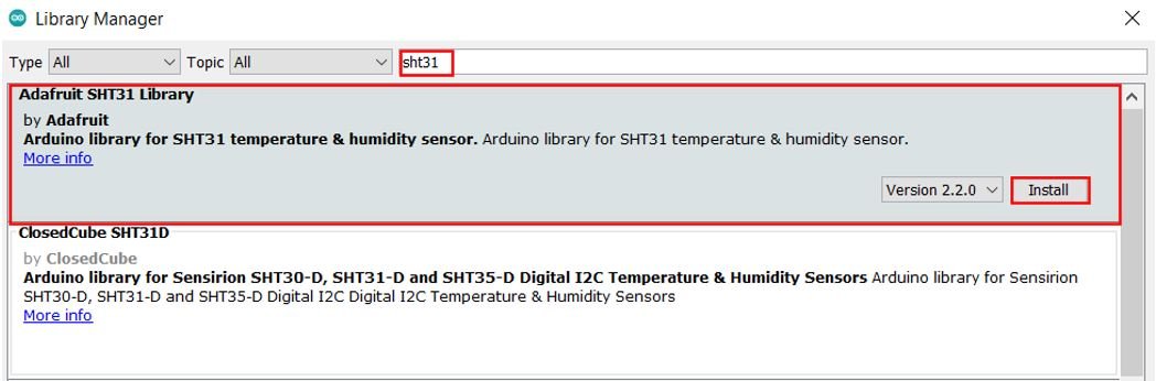
We will use the Library Manager in our Arduino IDE to install the latest versions of the libraries. Open your Arduino IDE and go to Sketch > Include Libraries > Manage Libraries. Type Adafruit SHT31 in the search bar and install the latest version.
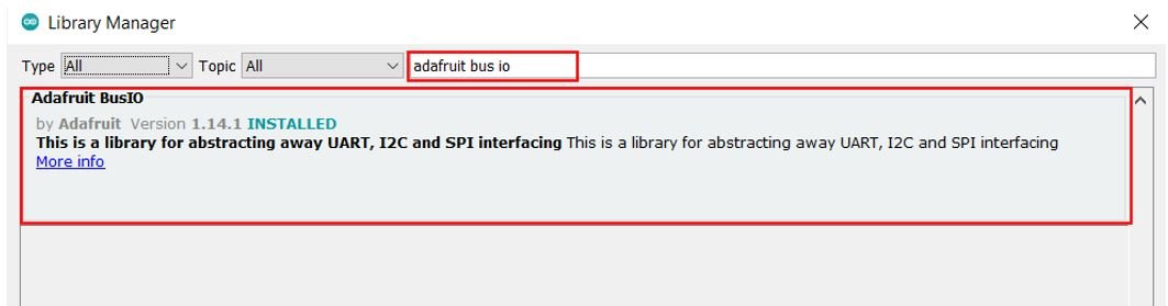
Type Adafruit BusIO in the search bar and install it as well.
Arduino Code – Get SHT31 Readings on Arduino Serial Monitor
This sketch displays current temperature and humidity readings on Arduino serial monitor after every second.
#include <Arduino.h>
#include <Wire.h>
#include "Adafruit_SHT31.h"

Adafruit_SHT31 sht31 = Adafruit_SHT31();

void setup() {
  Serial.begin(115200);

  if (! sht31.begin(0x44)) {
    Serial.println("Check circuit. SHT31 not found!");
    while (1) delay(1);
  }
}

void loop() {
  float temp = sht31.readTemperature();
  float hum = sht31.readHumidity();

  if (! isnan(temp)) {
    Serial.print("Temperature(°C): ");
    Serial.print(temp);
    Serial.print("\t\t");
  } else {
    Serial.println("Failed to read temperature!");
  }

  if (! isnan(hum)) {
    Serial.print("Humidity(%): ");
    Serial.println(hum);
  } else {
    Serial.println("Failed to read humidity!");
  }

  delay(1000);
}
How Code Works?
Now, let us understand how each part of the code works.
The code starts with including all the necessary libraries which are needed for the proper functionality of the code. The Wire.h will allow us to communicate through the I2C protocol. The Adafruit_SHT31.h library will enable us to initialize and read the SHT31 sensor.
#include <Arduino.h>
#include <Wire.h>
#include "Adafruit_SHT31.h"
Next we create the Adafruit_SHT31 object called ‘sht31.’
Adafruit_SHT31 sht31 = Adafruit_SHT31();setup()
Inside the setup() function, we start the serial communication at a baud rate of 115200 and then initialize the SHT31 sensor. If the sensor initialization is not a success, a relevant message will be printed on the serial monitor.
void setup() {
  Serial.begin(115200);

  if (! sht31.begin(0x44)) {
    Serial.println("Check circuit. SHT31 not found!");
    while (1) delay(1);
  }
}
loop()
Inside the loop() function, the Arduino first obtains the SHT31 sensor readings after every second and stores them in their respective float variables, ‘temp’ for temperature and ‘hum’ for humidity. Temperature readings are acquired through sht31.readTemperature(). Humidity readings are accessed using the sht31.readHumidity() function. If the sensor fails to output correct readings, the serial monitor will print a failure message regarding it.
void loop() {
  float temp = sht31.readTemperature();
  float hum = sht31.readHumidity();

  if (! isnan(temp)) {
    Serial.print("Temperature(°C): ");
    Serial.print(temp);
    Serial.print("\t\t");
  } else {
    Serial.println("Failed to read temperature!");
  }

  if (! isnan(hum)) {
    Serial.print("Humidity(%): ");
    Serial.println(hum);
  } else {
    Serial.println("Failed to read humidity!");
  }

  delay(1000);
}
Demonstration
In Arduino IDE, click Tools > Board and select Arduino.

Now, click Tools > Port and choose the port which you are using. Now, upload the code by clicking on the upload button.
After you have uploaded the following code on your Arduino development board, press the ENABLE button as follows:

In your Arduino IDE, open up the serial monitor and set the baud rate to 115200. The serial monitor will start displaying the temperature and humidity readings along with the units. New readings will be displayed after every second.

Display SHT31 Sensor values on OLED Display
In this section, we will see how to display SHT31 sensor readings on a 0.96 SSD1306 OLED display using Arduino IDE and Arduino.

You can read this in-depth guide on OLED interfacing with Arduino:
Installing SSD1306 OLED Library in Arduino IDE
To use the OLED display in our project, we have to install the Adafruit SSD 1306 library in Arduino IDE. Follow the steps below to successfully install it.
Open Arduino IDE and click on Sketch > Library > Manage Libraries. The following window will open up.

Type ‘SSD1306’ in the search tab and install the Adafruit SSD1306 OLED library.

Schematic – OLED with Arduino and SHT31
You will need the following components
- Arduino
- SHT31 Sensor Module
- SSD1306 OLED
- Breadboard
- Jumper wires
The table below shows the terminals of the three devices which should be connected together.
| OLED Display | Arduino | SHT31 |
|---|---|---|
| VCC | 5V | VIN |
| GND | GND | GND |
| SCL | A5 | SCL |
| SDA | A4 | SDA |
Assemble the circuit as shown in the schematic diagram below:

As you can see above, we have connected all the VCC terminals with 5V pin of Arduino. The SCL terminals are connected with A5 and the SDA terminals are connected with A4. The grounds are also common.
Arduino Sketch to Display SHT31 Readings on OLED
Copy the following code to your Arduino IDE and upload it to the Arduino after assembling the above circuit diagram.
#include <Arduino.h>
#include <Wire.h>
#include "Adafruit_SHT31.h"
#include <Adafruit_GFX.h>
#include <Adafruit_SSD1306.h>

Adafruit_SHT31 sht31 = Adafruit_SHT31();
Adafruit_SSD1306 display = Adafruit_SSD1306(128, 64, &Wire, -1);

void setup() {
  Serial.begin(115200);

  if (! sht31.begin(0x44)) {
    Serial.println("Check circuit. SHT31 not found!");
    while (1) delay(1);
  }

  display.begin(SSD1306_SWITCHCAPVCC, 0x3C);
   // init done
  display.display();
  delay(100);
  display.clearDisplay();
  display.display();
  display.setTextColor(WHITE);
}

void loop() {
  float temp = sht31.readTemperature();
  float hum = sht31.readHumidity();

  if (! isnan(temp)) {
    Serial.print("Temperature *C = ");
    Serial.print(temp);
    Serial.print("\t\t");
  } else {
    Serial.println("Failed to read temperature!");
  }

  if (! isnan(hum)) {
    Serial.print("Humidity % = ");
    Serial.println(hum);
  } else {
    Serial.println("Failed to read humidity!");
  }

  display.setCursor(0,0);
  display.clearDisplay();

  display.setTextSize(1);
  display.setCursor(0,0);
  display.print("Temperature: ");
  display.setTextSize(2);
  display.setCursor(0,10);
  display.print(temp);
  display.print(" ");
  display.setTextSize(1);
  display.cp437(true);
  display.write(167);
  display.setTextSize(2);
  display.print("C");

  // display humidity
  display.setTextSize(1);
  display.setCursor(0, 35);
  display.print("Humidity: ");
  display.setTextSize(2);
  display.setCursor(0, 45);
  display.print(hum);
  display.print(" %");

  display.display();
  delay(1000);
}
How the Code Works?
The maximum portion of the code is the same as we have discussed earlier except for the OLED display part. Therefore, we will only explain the OLED display part here.
We will first include all the required libraries for the SHT31 sensor as well as the OLED display which we just installed before.
#include <Arduino.h>
#include <Wire.h>
#include "Adafruit_SHT31.h"
#include <Adafruit_GFX.h>
#include <Adafruit_SSD1306.h>
Now, we will create another object named ‘display’ which will be handling the OLED display. Also, define the size of the OLED display by passing arguments to the Adafruit_SSD1306() function.
Adafruit_SSD1306 display = Adafruit_SSD1306(128, 64, &Wire, -1);Initialize the OLED display by calling the begin() method on the display object.
display.begin(SSD1306_SWITCHCAPVCC, 0x3C); Next, we will clear the OLED screen by calling clearDisplay() function. Also, we set the color of the text using setTextColor() function and pass WHITE as an argument. If we have a dark background, we will display our text in white and if we have a bright background then we will display the text in black.
  display.clearDisplay();
  display.display();
  display.setTextColor(WHITE);
Display Readings on the OLED
Inside the loop() function, we obtain the SHT31 sensor readings and print them on the OLED display.
We display the temperature and humidity values on the serial monitor on the OLED one by one. This block of code displays SHT31 sensor values on OLED and updates the values after every 1 second.
 display.setCursor(0,0);
  display.clearDisplay();

  display.setTextSize(1);
  display.setCursor(0,0);
  display.print("Temperature: ");
  display.setTextSize(2);
  display.setCursor(0,10);
  display.print(temp);
  display.print(" ");
  display.setTextSize(1);
  display.cp437(true);
  display.write(167);
  display.setTextSize(2);
  display.print("C");

  // display humidity
  display.setTextSize(1);
  display.setCursor(0, 35);
  display.print("Humidity: ");
  display.setTextSize(2);
  display.setCursor(0, 45);
  display.print(hum);
  display.print(" %");

  display.display();
  delay(1000);
In the above code, the setTextSize() function is used to set the size of the font. We used low size for simple text such as “Temperature” and “Humidity” and high size font to display actual temperature and humidity readings. We will use the setCursor() function to denote the x and the y-axis position from where the text should start. Finally, the print() function writes the text on the defined position.
Demonstration
To see the demonstration of the above code, upload the code to Arduino. But, before uploading code, make sure to select the Arduino board from Tools > Board and also select the correct COM port to which the Arduino board is connected from Tools > Port.
Once the code is successfully uploaded to the board, the OLED will start displaying the readings.

Video demo:
You may also like to read:
- MPU9250 9-DOF Gyro Accelerator Magnetometer Module with Arduino
- Arduino with BMP180 Atmospheric Pressure and Temperature sensor
- MAX30102 Pulse Oximeter and Heart Rate Sensor with Arduino
- MAX6675 K-Type Thermocouple with Arduino
- HC-SR04 Ultrasonic Sensor Interfacing with Arduino – Distance Measurement Example
- DHT11 DHT22 with Arduino
- Interface MQ3 Alcohol Sensor Module with Arduino
Very interresting articles found in this blog.