This topic will explore the pin configuration, interfacing with microcontroller/Arduino, features, and applications of AD8232 ECG module. The module AD8232 uses AD8232 analog IC. AD8232 IC is the main component of this ECG module. This chip performs three functions on small bi-potential signals in noisy conditions, such as extraction, amplification, and filtration. The final filtered signal provides a plot of an Electrocardiogram (ECG) of the heart, representing the heart’s electrical activity.

ECGs output generally contains extreme noise. AD8232 chip helps to remove PR and QT intervals by acting as a heart rate monitor.
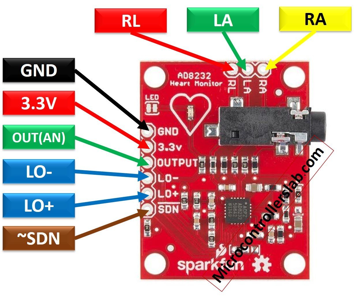
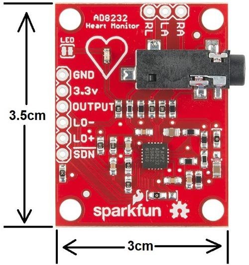
AD8232 ECG module Pinout Diagram
The following figure shows the pinout diagram of the ECG module. From this IC total of nine pins have been exposed on the pinout and provided in the form of an AD8232 ECG module for user-friendly interface and proper safety protection to IC.
Pin Configuration
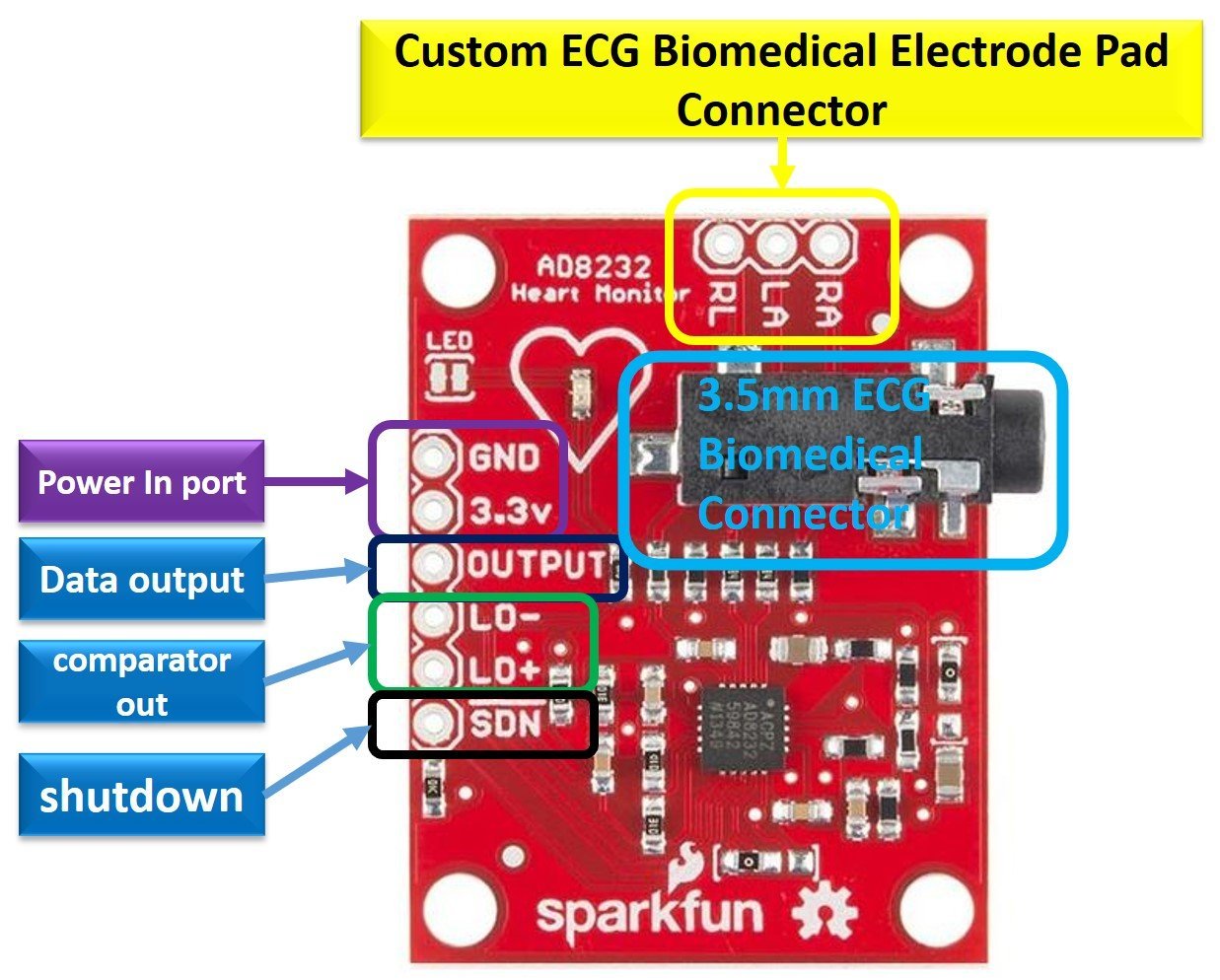
The ECG module AD8232 components can be divided into the following categories.
- Power Input Pins (3.3, GND)
- Electrode pad connector pins (RA, LA, RL, 3.5 mm female jack)
- Data output pin (Output)
- Leads off detection output pins(LO-, LO+)
- Shutdown control pin(~SND)
- LED
A detailed description of each Pin is given below.
ECG Electrode Connector Pins
LA ( Left ARM)
LA is the positive input (+IN) of the instrumentation amplifier of IC AD8232. A signal from the electrode connected to the left arm of the human body is received here.
RA (Right ARM)
RA is the negative input (-IN) of the instrumentation amplifier of IC AD8232. A signal from the electrode connected to the right arm of the human body is received here.
RL (Right LEG)
RL is a green color biomedical electrode acts as an electrode input and connected to the right leg of the human body.
3.5 mm Female Biomedical Electrode Connector Jack
This connector has been provided as an alternate of RA, LA, RL pins. We can connect three electrodes to this connector instead of RA, LA, and RL pins using a 3.5mm male jack. There are two methods to detect the heartbeat: the two-electrode method and Three electrode method. Two Electrodes method uses the AC signal, and the Three Electrodes method uses DC signal. To detect which method is being used, LEAD OFF DETECTION is implemented in this module.
ECG Module Data Output and Comparator Pins
| Pin Name | Function | Details |
|---|---|---|
| LO+ | Lead OFF Positive | In DC Lead Off Detection mode, LO+ is LOW when electrode at +IN (of IC AD8232), i.e., LA (of module AD8232) is connected, and LO+ is HIGH when electrode at +IN (of IC AD8232) i.e. LA (of module AD8232) is disconnected. In AC Lead Off Detection mode, LO+ is LOW when electrodes at both +IN and –IN (of IC AD8232) i.e. LA and RA (of module AD8232) are connected, and LO+ is HIGH when the electrode at LA or RA is disconnected. |
| LO- | Lead OFF Negative | In DC Lead Off Detection mode LO- is LOW when electrode at –IN (of IC AD8232) i.e. RA (of module AD8232) is connected and LO- is HIGH when electrode at –IN (of IC AD8232) i.e., RA (of module AD8232) is disconnected. In AC Lead Off detection mode LO- is always LOW. |
| OUTPUT | This is an output pin at which a filtered analog signal is present, and it gives the electrical activity of the heart. This signal can be feed as an analog input to the Analogue to digital converter or microcontroller for analysis and visualization. |
Power supply Pins
| Pin Name | Function |
|---|---|
| 3.3 V | This is + ve Pin of 3.3V to power up the module. |
| GND | This is the Ground Pin of 3.3V to power up the module. |
| ~SDN ( Shut Down) | When ~SDN pin is set to low, the module enters low power shutdown mode. |
AD8232 ECG Module Interfacing with Microcontrollers
To analyze or visualize the electrical activity of the heartbeat following items are required.
- Electrode pads
- Connecting wires
- 3.5 mm male Jack
- AD8232 ECG Module
- Microcontroller
The figure below shows how to interface this module with any microcontroller for ECG:
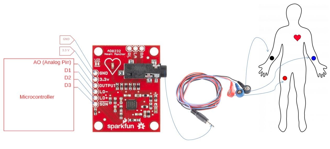
- ECG module is powered by connecting a power supply of 3.3 V at power pins.
- A set of biomedical electrodes connecting wires having 3 electrode pads at one end and a 3.5 mm male jack at the other end is used to carry electrical activity of the heart to the AD8232 module. 3 sensors are connected at the left arm, right arm, and right leg as per the color scheme shown in the figure above.
- The data received through the above-mentioned wires appear as an analog signal at the OUTPUT pin of module AD8232. This analog signal can be fed at the analog input pin of the microcontroller for further processing or visualization as a graph.
- LO- and LO+ are connected to digital input pins of the microcontroller to check whether a sensor is connected or not.
- ~SDN is connected to the digital output pin of the microcontroller to activate the low power mode of module AD8232.
AD8232 ECG Module interfacing with Arduino
To interface ECG module with Arduino, we require minimum of 5 pins Arduino such as two digital pins, one analog pin, 3.3v and GND pin. The following figure shows the connection diagram to interface Arduino with AD8232 with Arduino.
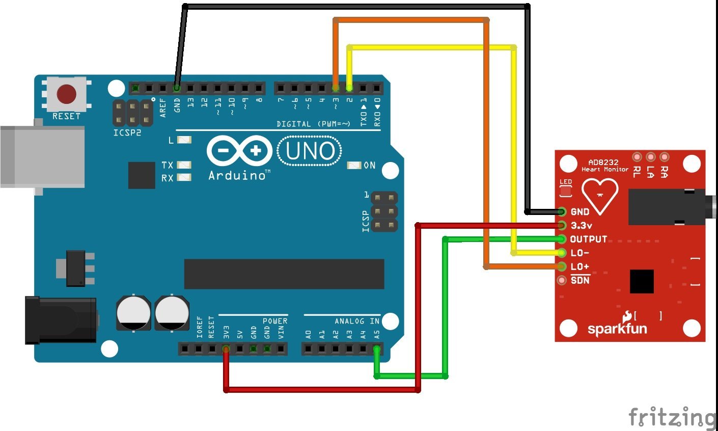
| Arduino | ECG Module |
|---|---|
| 3.3V | 3.3V |
| GND | GND |
| A5 | OUTPUT |
| D2 | LO- |
| D3 | LO+ |
After making connection diagram, connect 3.5mm biomedical three electrode pad connectors with black colour female jack. This electrode pad comes with colour coding such as:
- Red: RA (Right Arm)
- Yellow: LA (Left Arm)
- Green: RL (Right Leg)
Arduino Code
void setup() {
// initialize the serial communication:
Serial.begin(9600);
pinMode(3, INPUT); // Setup for leads off detection LO +
pinMode(2, INPUT); // Setup for leads off detection LO -
}
void loop() {
if((digitalRead(10) == 1)||(digitalRead(11) == 1)){
Serial.println('!');
}
else{
// send the value of analog input 0:
Serial.println(analogRead(A5));
}
//Wait for a bit to keep serial data from saturating
delay(1);
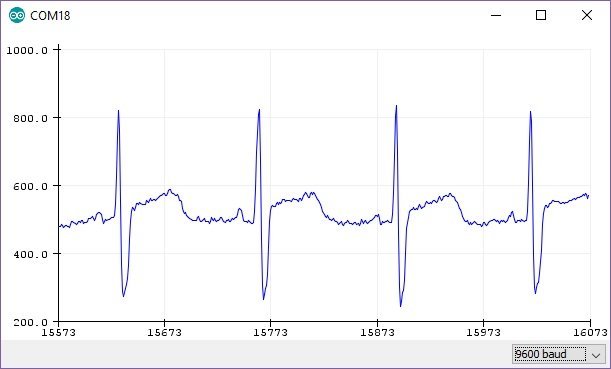
}Now upload this code to Arduino using Arduino IDE. After uploading code, you can visualize the output in the form graph on Arduino IDE plotter. In Arduino IDE, go to tools>Serial Plotter and set the baud rate to 9600. After that you will see an output like this on Arduino serial plotter.
AD8232 ECG module Features
- Analog easy to read output signal with microcontrollers
- Operating voltage: 2.5 to 3.3 VDC
- Operating current: 170 µA.
- Conventional ECGs are quite noisy. This module act as an operational amplifier to extract clear signal during PR and QT interval of the heartbeat.
- common-mode rejection ratio: 80 dB at 60 Hz.
- Electrostatic discharge for the human body model: 8 kV.
- Detect which lead is connected or disconnected.
- It has a shutdown pin which can be used to enter in energy-saving mode.
- Rated temperature range: 0 to 70 degrees centigrade.
- working temperature range from -40 to 85 degrees centigrade.
- Dimensions of 3.5 cm x 3 cm.
Applications
- Cost-effective alternative to conventional ECG.
- Fitness-related devices.
- Serve as a remote health monitor.
- It can be used in monitoring heartbeats during exercises.
Related Articles:
- Heart Rate Pulse Sensor Amped introduction
- RCWL0516 Microwave Distance Sensor Module with Arduino
- Heart beat pulse sensor interfacing with pic microcontroller
- CCPM Servo Consistency Master/Servo Motor Tester
- heart beat sensor with Arduino|heart pulse measurement
- TTP224 Four-Channel Touch Detector Module with Arduino
- WS2812B Addressable RGB LED Interfacing with Arduino
- 5V Dual Channel Relay Module Interfacing with Arduino
- Seven Segment Display Interfacing with Arduino