This article is about how to easily and massively expand digital outputs by using the 74HC595N shift register with Arduino Uno or Arduino Mega. Sometimes, in many electrical and embedded systems projects, there is a need to connect and operate more sensors or other output devices to the Arduino. However, there are no more output pins available on the Arduino board. To avoid this issue and extend the number of output ports, we can use the shift register IC74HC595N for serial in and parallel out. In this article, you will learn how to increase or expand the output ports of Arduino using a simple shift register.
This shift register IC74HC595N requires three input pins from Arduino and provides eight output pins. These extended pins are only used as output ports and can be used to operate or connect output devices such as LCD displays, Buzzers, speakers, LEDs, etc. For example, if you want to interface multiple seven-segment displays with Arduino, you will surely face the issue of having fewer output ports. Therefore, you can easily resolve this issue by using this method to expand the available output pins.
74HC595 Introduction
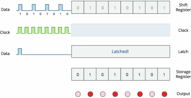
74HC595 IC is a 16-pin shift register IC consisting of a D-type latch along with a shift register inside the chip. It receives serial input data and then sends out this data through parallel pins. In addition to parallel outputs, it also provides a serial output. It has independent clock inputs for the shift register and D latch. This IC belongs to the HC family of logic devices which is designed for use in CMOS applications.
74HC595 has two built-in registers. The first one is a shift register and the second one is a storage register. Data serially transfers to shift register bit by bit. But it transfers to the storage register only when the data latch pin is active high.
74HC595 Pinout Diagram
If you look for 595 series shift registers, it has many variants and models available in the market. But all work the same way. They have the same pin configuration, electrical features, pinout diagram, and working principle. But this tutorial will be more focused on SN74HC595N by texas instruments.
Now, look at the pinout diagram. The tilt sign ~ shows that these pins operate on active low signals or on negative logic. We will look into the details of negative logic later on in this tutorial.
Related to output pins, because it is an 8-bit shift register. SN74HC595N has eight output pins from Q0-Q7.
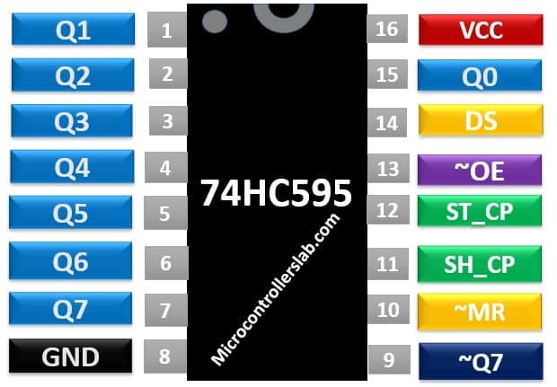
Pin Configuration Details
In this section, we see Pin Description of all pins along with their working and functionality.
Pin# 01, 02, 03, 04, 05, 06, 07, 15: Output pins
These eight pins are the output pins of the shift register. We should connect these pins with any peripheral where we want to display storage register data. Commonly used components are like LED, seven-segment displays, etc.
Pin# 08: GND
This is the ground pin and is connected to the ground of the circuit.
Pin# 09: Q7’
It is a non-inverted serial data output coming out of the eighth stage of a shift register. It is also used for cascading purposes. For instance, if we need 16 bits shift register. We can daisy-chain two 74HC595 ICs. To do this, simply connect ~Q7 pin with Serial input DS pin of 2nd 595 IC. Moreover, provides the same clock signal to both integrated circuits. In this way, two 74HC595 will work as a single 16-bit shift register. Furthermore, you can continue this process to connect as many ICs as you want to get more data width.
Pin# 10: ~MR
It is an asynchronous, active low master reset Input which is used to reset the shift register only. The 8-bit latch is not affected by this input. Applying a low signal at pin 10 will reset the shift register portion only.
Pin # 11: SH_CP
This is the clock input pin of a 74hc595 shift register. A data is shifted from the serial input pin to the 8-bit shift register on every positive transition of the clock signal applied at this pin.
Pin# 12: ST_CP
This is the active high, clock input pin of a storage register. A positive transition of a signal at this pin is used to update the data to the output pins.
Pin# 13: ~OE
The Output Enable pin is active low. When this pin is low, the data in the storage register appears at the output. On applying high signals, outputs are turned off by forcing them into the high-impedance state. However, serial output is not affected at all. For normal operations, it is kept low.
Pin# 14: DS
This is the serial data input pin, where input data is provided.
Pin# 16: Vcc
A positive power supply is provided at this pin.
74HC595 Features
- It is a shift register with 8-bit serial input and 8-bit serial or 3-state parallel outputs.
- The operating voltage of this IC is from 2V to 6V.
- The output voltage is equal to the operating voltage of this IC .
- It is based on CMOS logic and therefore consumes a very low power of 80uA.
- The output source/sink current is 35mA.
- It has a characteristic of high noise immunity.
- It can be easily cascaded through pin 9 with more IC to get more outputs.
- The maximum clock frequency is 25Mhz @4.5V.
- Schmitt trigger action is provided on all inputs.
Alternative Shift Registers
Where to use 74HC595?
Do you ever wonder, how an embedded engineer controls hundreds of series or parallel connected light-emitting diodes with the help of a microcontroller that have very few general-purpose I/O pins? Additionally, You want to control more than 8 servo motors and you have only 2-3 GPIO pins of a microcontroller. How you will solve this problem? How you will control an LED Matrix of different dimensions such as 8×8, 16×16, 32×32 with minimum GPIO pins of a microcontroller? The simple answer is a 74HC595 shift register.
In most of the applications, you need more outputs for interfacing LEDs or any other devices such as seven segments, 16 segments, LED flasher, etc. This IC is very handy to use. For increasing the output pins, you can interface this IC with different microcontrollers such as Arduino Uno, PIC Microcontroller, Atmel, etc. You can use this IC in designing projects which require controlling multiple outputs.
74HC595 Shift Register Working Principle
As mentioned earlier, the internally 74HC595 shift register consists of two registers such as shift register and storage register. Both are 8-bit wide. The first one is responsible to accept data input on every positive edge of the clock and it keeps receiving data. But data from the shift register transfer to the storage register only when we apply an active high signal to latch input pin.
How to use 74HC595 Shift Register?
- It has eight outputs and 3 input pins which include a data pin, storage resistor clock pin, and shift register clock pin. Connect pin8 to ground and pin16 to +5V voltage supply.
- The output enable pin (~OE) should be grounded to enable the output pins of the shift register. The master reset pin will clear the memory of a shift register if it is applied with a low signal. That’s why it should be kept high.
- When the positive edge transition occurs on pin 11, the shift register will accept the inputs applied on the data line.
- The outputs of the storage register are connected to the input pins of the D-latch/storage resistor.
- These inputs are updated on the latch output when a positive edge transition occurs at pin 12.
Most importantly, If you need to cascade multiple IC’s together then pin 9 is connected to the data pin of another shift register IC.
Proteus Simulation
This video is a simulation of the 74HC595 Shift register. we will apply different serial inputs and check the output on the bar graph. First, let’s apply the 11110000 serial input and see the output. We enable latch signal after 8 seconds because we are sending serial data to 74hc595 after every one second. Therefore, a total of 8 bits of data required 8×1=8 seconds to shift serially.
Therefore, we can load data to the output register after 8 seconds when all 8 bits
are transferred. Now let’s apply different input data.
As you have seen from video of Proteus simulation, we get output according to serial data input as soon as we apply latch signal after the transfer of 8 bits of data.
74HC595 Shift Register Interfacing with Arduino
In this example, we will see how to interface the 74HC595 shift register IC with Arduino.
In this example, we will control 8 LEDs with a 74HC595 shift register and Arduino. To interface 74HC595 with Arduino, we will use three digital pins. All three pins will be used as digital output pins. These three pins are clock, data and latch pins.
Connection Diagram
As we mentioned earlier, shift register takes one-bit data serially on every positive edge transition of clock signal and shift register holds this data. To send shift register data to the output register or output pins (Q0-Q7), we should activate the latch pin by providing a positive edge pulse. Therefore, one pin of the Arduino will provide a latch signal.

Now make connections of Arduino With 74HC595 shift register according to this table. We connect the enable pin (~OE) with ground which activates this IC. Because it is an active-low pin. We can also control this pin through an Arduino digital pin. But just to save Arduino Pin, it is better to provide a hardwired signal by directly connecting it with ground.
| Arduino | 74HC595 |
|---|---|
| D11 | Output Register Clock (Pin12) |
| D9 | Shift Register Clock (Pin10) |
| D12 | Data in (Pin14) |
| GND | Output Enable (Pin13) |
| +5V | Shift Register Clear (Pin10) |
| +5V | Power (Pin16) |
| GND | Ground (Pin8) |
LEDs connections
Connect eight output pins with LEDs through current limiting resistors. This circuit will turn on all these LEDs sequentially with some delay.
Arduino Code
This code is for controlling LEDs with a 74HC595 serial shift register.
#define LATCH_pin 11      // (11) ST_CP [RCK] on 74HC595
#define CLCOK_pin  9      // (9) SH_CP [SCK] on 74HC595
#define DATA_pin 12     // (12) DS [S1] on 74HC595

void clock_signal(void){
   digitalWrite(CLCOK_pin, HIGH);
    delayMicroseconds(500);
   digitalWrite(CLCOK_pin, LOW);
    delayMicroseconds(500);
}
void latch_enable(void)
   {
    digitalWrite(LATCH_pin, HIGH);
    delayMicroseconds(500);
    digitalWrite(LATCH_pin, LOW);
    }
void send_data(unsigned int data_out)
{
    int i;
    unsigned hold;
    for (i=0 ; i<8 ; i++)
    {
        if ((data_out >> i) & (0x01))
        digitalWrite(DATA_pin,HIGH);
        else
        digitalWrite(DATA_pin,LOW);

        clock_signal();
    }
    latch_enable(); // Data finally submitted
}

void setup()
{
  pinMode(LATCH_pin , OUTPUT);
  pinMode(DATA_pin , OUTPUT);
  pinMode(CLCOK_pin , OUTPUT);
  digitalWrite(LATCH_pin, LOW);      // (11) ST_CP [RCK] on 74HC595
  digitalWrite(CLCOK_pin, LOW);      // (9) SH_CP [SCK] on 74HC595
  digitalWrite(DATA_pin, LOW);     // (12) DS [S1] on 74HC595
  Serial.begin(9600);
}

void loop()
{

        send_data(0b00000000);
        delay(1000);
        send_data(0b10000000);
        delay(1000);
        send_data(0b01000000);
        delay(1000);
        send_data(0b00100000);
        delay(1000);
        send_data(0b00010000);
        delay(1000);
        send_data(0b00001000);
        delay(1000);
        send_data(0b00000100);
        delay(1000);
        send_data(0b00000010);
        delay(1000);
        send_data(0b00000001);
        delay(1000);
}
How code works?
Configure Arduino Digital Pins
First, we need to define GPIO pins of the Arduino microcontroller that we will use as data, clock, and latch pins. Hence, we used the #define directive to define pins. We used D12, D11, and D9 pins of Arduino as DATA_pin, LATCH_pin, and CLCOK_pin respectively.
#define LATCH_pin 11      // (11) ST_CP [RCK] on 74HC595
#define CLCOK_pin  9      // (9) SH_CP [SCK] on 74HC595
#define DATA_pin 12     // (12) DS [S1] on 74HC595
74HC494 Clock Signal Function
First, we declare a function that provides a clock signal to the ST_CP pin of the 74HC595 shift register. This clock_signal() function generates a clock signal with a time period of 1ms or a frequency of 1KHz. Because on-time is 500 microseconds and off-time is also 500 microseconds. We used a delayMicroseconds() function of the Arduino IDE compiler to add a delay between on and off time of the clock signal.
void clock_signal(void){
   digitalWrite(CLCOK_pin, HIGH);
    delayMicroseconds(500);
   digitalWrite(CLCOK_pin, LOW);
    delayMicroseconds(500);
}
Remember, we can also achieve this using the PWM of Arduino and through SPI communication also. But for the sake of simplicity, we use a delay method to generate a clock signal.
Providing Latch Signal to 74HC595
As we have seen earlier, serial data input pin transfers 8-bit data serially to the internal shift register of 74HC595. But this data does not reflect on output pins unless we apply a positive edge signal on the latch pin (SH_CP). This latch_enable() routine provides a latch enable signal. Whenever we want to send data to output pins( Q0-Q7), we will call this function inside the code.
void latch_enable(void)
   {
    digitalWrite(LATCH_pin, HIGH);
    delayMicroseconds(500);
    digitalWrite(LATCH_pin, LOW);
    }
Sending data Serially
Now we know that we have defined clock signal and latch enable functions. The main thing which is left now is to define a function to transfer 8-bit data serially to the DS_pin of 74HC595 IC. For this purpose, we declare a send_data(unsigned int data_out) function.
void send_data(unsigned int data_out)
{
    int i;
    unsigned hold;
    for (i=0 ; i<8 ; i++)
    {
        if ((data_out >> i) & (0x01))
        digitalWrite(DATA_pin,HIGH);
        else
        digitalWrite(DATA_pin,LOW);

        clock_signal();
    }
    latch_enable(); // Data finally submitted
}
We call this function with 8-bit data as an input argument like this send_data(2). We can also write send_data(2) like this send_data(0b00000010). with this expression, we pass data to function in binary format “send_data(0b00000010)”.
Inside send_data() routine, we need to send 8-bit data bit-by-bit serially. Because this function accepts 8-bit data with the data_out variable. To send this 8-bit data serially, we make use of the left-shift operator and logical AND gate. “For” loop executes 8 times because data is 8-bit wide. Furthermore, we also call clock_signal() after sending 1-bit Data_pin. Because data transition occurs on the positive edge of the clock only. After transferring all 8-bits to the shift register, the latch_enable function call moves the data to the output pins.
Serial data transmission starts data transfer with the most significant bit first and so on and LSB transfers at the end.
Setup Function
Inside the setup() code, we initialize the digital pins D12, D11, and D9 as digital output pins. pinMode() function is used to configure pic microcontroller pins as an output or input.
pinMode(LATCH_pin , OUTPUT);
pinMode(DATA_pin , OUTPUT);
pinMode(CLCOK_pin , OUTPUT);
digitalWrite(LATCH_pin, LOW);      // (11) ST_CP [RCK] on 74HC595
digitalWrite(CLCOK_pin, LOW);      // (9) SH_CP [SCK] on 74HC595
digitalWrite(DATA_pin, LOW);     // (12) DS [S1] on 74HC595
In the end, for demonstration purposes, we send data to turn on eight LEDs sequentially. Starting from Q0-Q7. As you can see from these lines, at the start, we send MSB one and all other bits zero. But it will appear on the Q0 pin and the rest of the pins will be zero. Similarly, logic high appears on other pins with a delay of 1000ms.
 send_data(0b00000000);
        delay(1000);
        send_data(0b10000000);
        delay(1000);
        send_data(0b01000000);
        delay(1000);
        send_data(0b00100000);
        delay(1000);
        send_data(0b00010000);
        delay(1000);
        send_data(0b00001000);
        delay(1000);
        send_data(0b00000100);
        delay(1000);
        send_data(0b00000010);
        delay(1000);
        send_data(0b00000001);
        delay(1000);
Demo

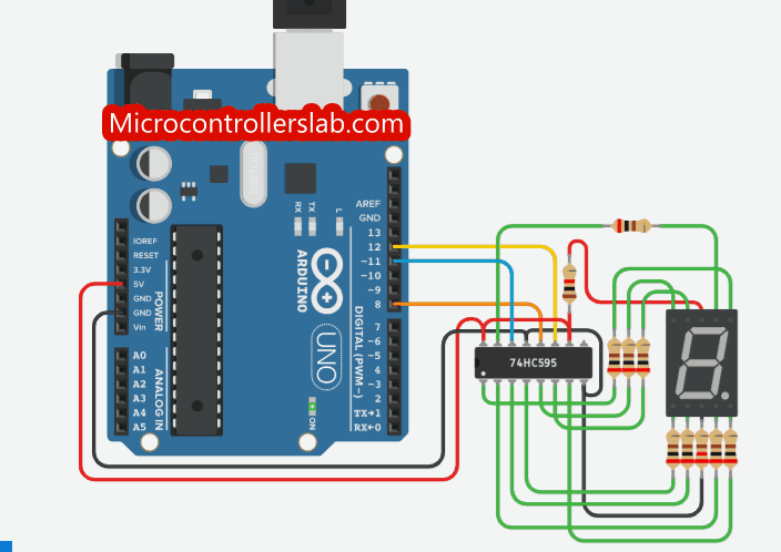
74HC595 Interfacing with 7 Segment Display and Arduino
In this section, we will learn to interface 74HC595 with a 7-segment display and Arduino. By using a 74HC595 shift register to drive 7-segment displays with Arduino, we can save GPIO pins of Arduino.
Why use 74HC595 to drive 7-Segment Displays?
In the last tutorial on 7-segment display interfacing with Arduino, we have seen that if we interface one 7-segment device directly with Arduino, we will need 8 digital pins of Arduino. Similarly, if we use two-digit, three-digit, four-digit seven-segment displays, we will need more GPIO pins, even if we use the multiplexing techniques to save microcontroller pins.
Therefore, by using a 74HC595 serial shift register, we can save Arduino digital pins and can use them for other purposes. For instance, if we use this serial shift register IC, we can interface 7-segment with Arduino by using three pins only, instead of using 8 digital pins.
Schematic Diagram
This schematic diagram shows the connection between shift regiser IC, Arduino, and common cathode type single digit 7-segment.

As you can see from the schematic diagram, we connect 74HC595 with the display unit in the sequence of (Q0-Q7) output pins according to this table.
| 74HC595 | 7-Segment pins |
|---|---|
| Q0 | A |
| Q1 | B |
| Q2 | C |
| Q3 | D |
| Q4 | E |
| Q5 | F |
| Q6 | G |
| Q7 | DP |
Arduino Sketch
This Arduino sketch displays numbers from 0 to 9 on a single-digit 7-segment display with a delay of one second.
#define LATCH_pin 8 // (8) ST_CP [RCK] on 74HC595
#define CLCOK_pin 12     // (12) SH_CP [SCK] on 74HC595
#define DATA_pin 11    // (11) DS [S1] on 74HC595

unsigned char binary_pattern[] = {
  	0b11111010,
	0b01100000,
  	0b11011100,
  	0b11110100,
  	0b01100110,
  	0b10110110,
  	0b10111110,
  	0b11100000,
  	0b11111110,
  	0b11100110,
};
unsigned int counter=0;

void clock_signal(void){
   digitalWrite(CLCOK_pin, HIGH);
    delayMicroseconds(500);
   digitalWrite(CLCOK_pin, LOW);
    delayMicroseconds(500);
}
void latch_enable(void)
   {
    digitalWrite(LATCH_pin, HIGH);
    delayMicroseconds(500);
    digitalWrite(LATCH_pin, LOW);
    }
void send_data(unsigned int data_out)
{
    int i;
    unsigned hold;
    for (i=0 ; i<8 ; i++)
    {
        if ((data_out >> i) & (0x01))
        digitalWrite(DATA_pin,HIGH);
        else
        digitalWrite(DATA_pin,LOW);

        clock_signal();
    }
    latch_enable(); // Data finally submitted
}

void setup()
{
  pinMode(LATCH_pin , OUTPUT);
  pinMode(DATA_pin , OUTPUT);
  pinMode(CLCOK_pin , OUTPUT);
  digitalWrite(LATCH_pin, LOW);      // (11) ST_CP [RCK] on 74HC595
  digitalWrite(CLCOK_pin, LOW);      // (9) SH_CP [SCK] on 74HC595
  digitalWrite(DATA_pin, LOW);     // (12) DS [S1] on 74HC595
  Serial.begin(9600);
}

void loop()
{

       send_data(binary_pattern[counter]);
       counter++;
       if(counter>9)
       counter =0;
        delay(1000);
}
How Code works?
This code works similarly to the code that we discussed in the last section except for the “while” loop part. First, we initialize the display codes for a common cathode type seven-segment display using an array.
unsigned char binary_pattern[] = {
  	0b11111010,
	0b01100000,
  	0b11011100,
  	0b11110100,
  	0b01100110,
  	0b10110110,
  	0b10111110,
  	0b11100000,
  	0b11111110,
  	0b11100110,
};
Inside the while loop, we pass display codes values to the send_data() function with the help of a counter variable. Counter variable increments after every one second and are used to display updated values. When the counter value becomes equal to 9, we reset the counter value to zero.
 send_data(binary_pattern[counter]);
         counter++;
         if(counter>9)
         counter =0;
         delay_ms(1000);
Simulation result:
SN74HC595 Applications
This IC has a multitude of applications and is used in wide arrays of products such as computer peripherals, Appliances, etc. Few applications are enlisted below:
- Holding Data for a long time period
- Serial to Parallel Data Conversion
- General Purpose Logic
- Controlling LED’s
2D Diagram
It is available in 16-pin PDIP, GDIP, PDSO packages. The dimensions of the PDSO package are given below.

Datasheet
Related Projects and Tutorials: