We can see biometric authentication almost everywhere around us, fingerprint scanning being the most frequent one. From our smartphones to door locks to cars, fingerprint scanning is being implemented to provide security, privacy, and ease. A digital key is a perfect replacement for the ordinary keys.
GT511C3 Fingerprint Scanner Introduction
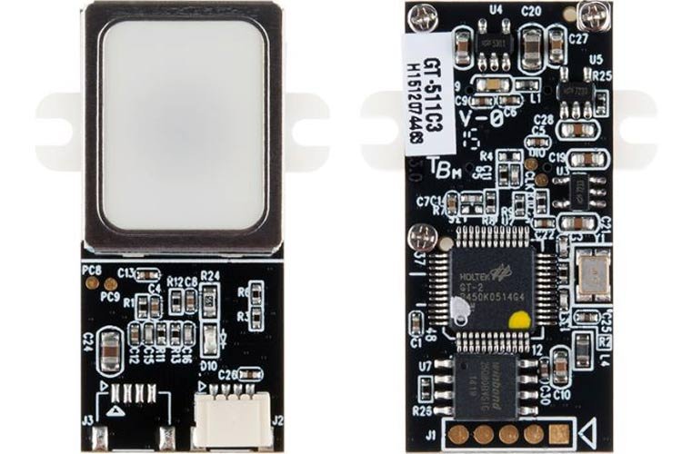
GT511C3 is a similar Fingerprint Scanner module introduced by ADH-Tech. It is a small module integrated with an Optic Sensor that communicates with the microcontrollers using TTL Serial. For this reason, the module has a Universal Asynchronous Receiver/Transmitter protocol.
The module comes with a high-performance 32-bit ARM Cortex M3 CPU, which does all the work. It has the capacity to store 200 different fingerprints in its database. All we need to do is give simple instructions to the module, scan and register the fingerprints, and get started with either of your DIY project or security checks, etc.
DS3231 Pinout
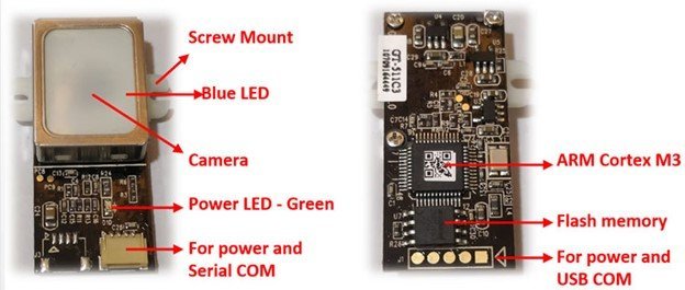
The following diagram shows the pinout of the GT511C3 Fingerprint Module:

- Camera and Blue LED: The optic sensor has a camera and blue LEDs to capture clear pictures of the fingerprints.
- Communication Ports: The module can communicate in two ways, either serially using UART or through USB protocol. It powers the module as well.
- CPU and Memory: ARM Cortex IC with an EEPROM for storing and processing the fingerprints.
- Green Power LED: An LED for power indication. When the module is energized, the LED will glow Green.
Pin Configuration
Let us discuss the pinout of the GT511C3 Fingerprint Module.
The pin configuration detail in tabular is mentioned below:
| Pin Name | Function |
|---|---|
| VCC | Power Supply pin |
| GND | Ground pin |
| TX | UART Transmission pin |
| RX | UART Reception pin |
GT511C3 Fingerprint Scanner Features and Specifications
The technicals and specifications of this awesome module are listed below:
- Operating Voltage: 3.3 – 6 Volts
- Operating Current: <130 mA
- Operational Temperature: -200C – 600C
- Operational Humidity: 20% – 80%
- CPU: ARM Cortex M3 Core (Holtek HT32F2755)
- Sensor Effective Area: 14×10.5mm
- Maximum fingerprints Capacity: 200
- Image Size: 202×258 pixels
- Image Resolution: 450 dpi
- Template Size: 496 Bytes(Template) + 2 Bytes(checksum)
- False Acceptance Rate: < 0.001%
- False Rejection Rate: < 0.1%
- Enrollment Time: < 3sec for three fingerprints
- Identification Time: < 1.0% for 200 fingerprints
- UART Baud Rate: 9600 bps
- USB v1.1(Full speed)
Some of its extra features include:
- The chip has an Ultra-thin optic sensor and SmackFinger 3.0 fingerprint algorithm.
- High-speed and accurate fingerprint recognizing technology
- Communication may take place through UART or USB interface.
- It can Read/Write templates from/to the device.
- The matching is based on 1:1 verification and 1:N identification.
- A 3600 finger recognition attribute
How does the GT511C3 Fingerprint Scanner work?
GT511C3 Fingerprint Scanner module is different from the capacitive and ultrasonic scanners. It is integrated with the optic sensor. The module’s optic sensing region has a camera and an array of blue LEDs, which will provide light to the camera to take clear pictures of the image. We can see that the sensing region is also capsuled with a metal case. The reason is to protect the sensor from the heating caused by the LEDs. The dimensions of each image are 202×258 pixels with 450 dpi. The patterns of the fingerprints are detected and processed using the algorithms by the ARM microcontroller unit. A fingerprint is enrolled within 3 seconds.
The sensor will assign an identification number to the fingerprint, and then it will be stored in the flash memory. As told earlier, the sensor has the capacity to enroll 200 fingerprint templates, so it can assign up to 200 ID numbers starting from 0 up to 199. This will help during the detection of the fingerprints. The sensor will compare the test fingerprint to all the templates stored using the SmackFinger 3.0 algorithm. As soon as the scanned fingerprint is distinguished, it will return the ID number. The lesser the number of enrolled templates faster the recognition will be.
The module commonly operates at 3.3 Volts and acquires 130mA of current. All of the communication takes place either serially or through USB protocol.
Programming the GT511C3 Module
Through USB
Connect the USB pads at the back of the module shown in the pinout to the computer’s USB port using Micro B USB Breakout. Once properly connected, we need to download the Software Development Kit SK_DEMO.exe software. The software provides access to the user to read/write/delete and distinguish the fingerprints. If we are using the USB COM port, then the software can scan the fingerprint image along with the scanner to recognize the test fingerprint.
Through UART
For coding Serially, connect the UART pins to the microcontroller. The transmission and reception will occur through TX and RX pins of the module with a 9600 baud rate. Once connected, use the concerned compilers and libraries for the code.
Software Development Kit SK_DEMO.exe software can also be used with Arduino if we want to by selecting specific options.
Though the module can be powered up using up to 6 Volts, the TX/RX pins are 3.3 Volts tolerant, so we must step-down the voltage. For this purpose, a potential divider circuit must be used to protect the pins and make them functional. Use 10k and 22k ohms of resistors to bring down the volts.
Interfacing GT511C3 Fingerprint Scanner with Arduino
This section deals with the interfacing of an Arduino microcontroller to the GT511C3 Fingerprint Scanner Module.
Connection Diagram
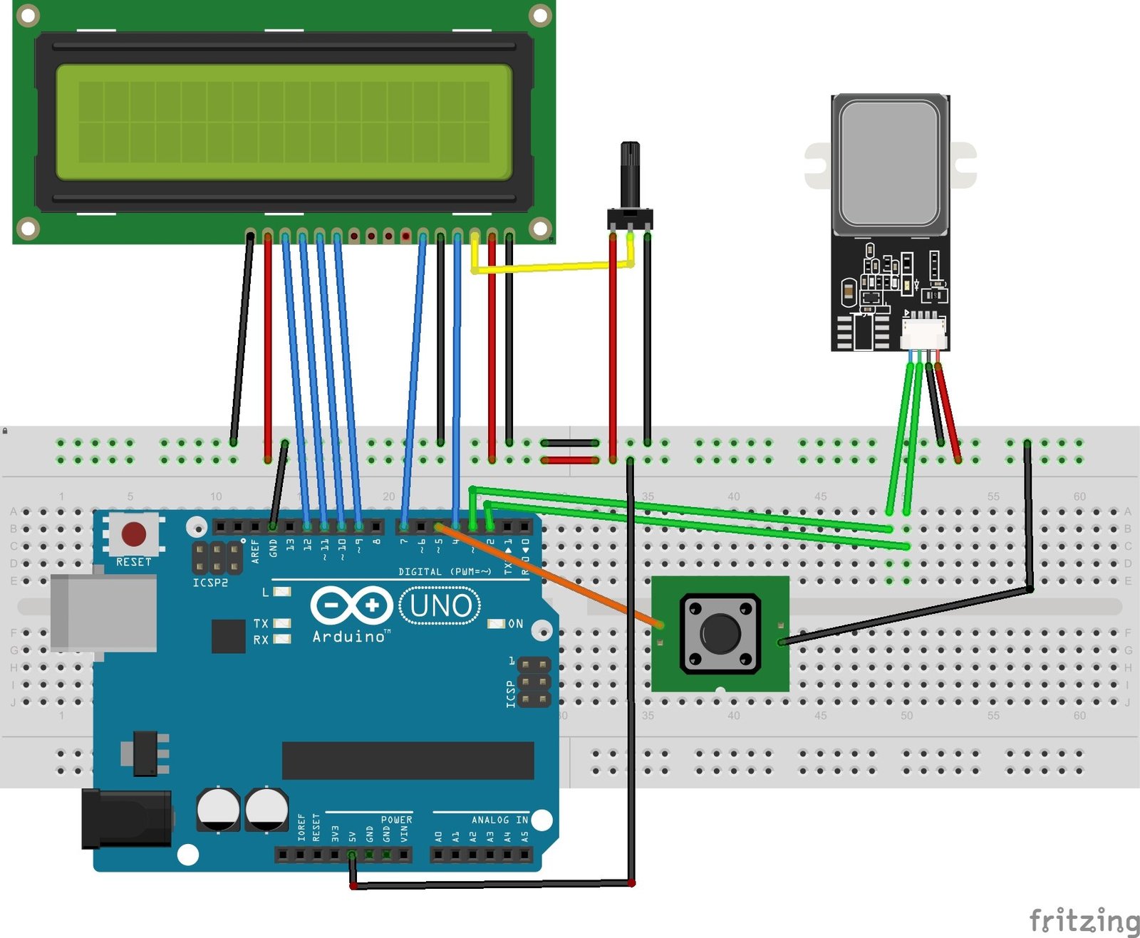
We are using an Arduino NANO, GT511C3 module, an LCD, a push button, and resistors to make a potential divider circuit.
- Connect the power supply pins of the module to the ground and the 5Volts pin of the Arduino. We can use the 3.3 Volts to power up the module but then we have to make sure that the current is enough for the sensor to work.
- Connect the TX and RX pins of the FPS to any of the digital pins of the Arduino to communicate serially. Also, connect the resistors with the TX and RX pins to lower down the voltage to 3.3Volts.
- Connect the 4-bit LCD to the Arduino. It will display the messages according to the execution of the program. The LCD is also powered using Arduino’s 5 volts supply pin.
- Attach a push button to the module too. So, whenever the button is pressed the Sensor moves from the finger Scanning mode to the Enrollment mode.
The wiring diagram is provided below:
Installe Finger Print Scanner Library in Arduino IDE
The datasheet contains all the commands accustomed to the particular HEX values for Serial Communication. But it is easy to use the library written specifically for the module and link it to the code to perform enrolling and scanning of the fingers.
First, we need to install a library for AD9850 signal generator module in Arduino IDE. To install library, open Arduino IDE. Go to Tools > Library Manger.
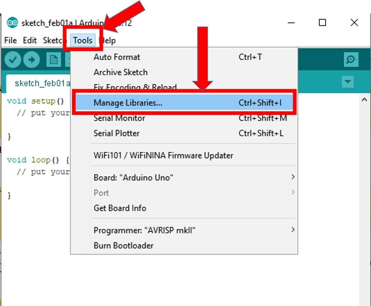
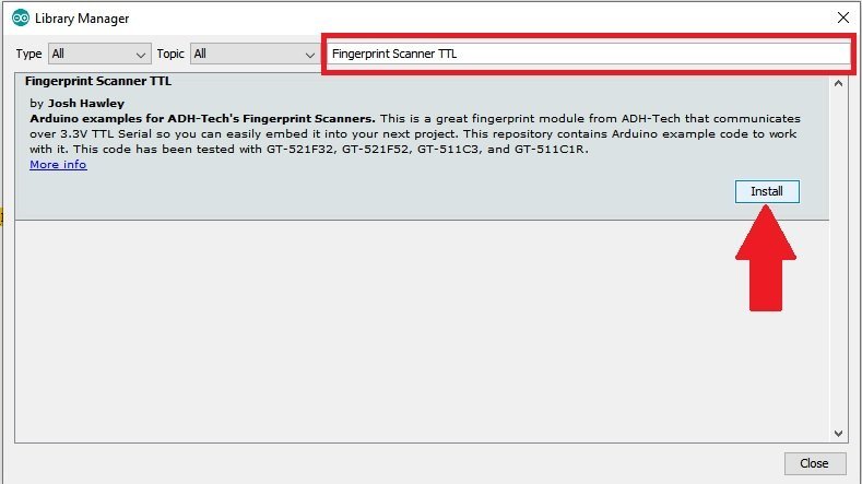
After that type “Fingerprint scanner TTL” in the search bar. You will get these options as shown in the picture. Select Fingerprint scanner TTL and click on the install button.
After installation, restart the Arduino IDE and now we can use the example sketches of this library.

Four Example Sketches
- FPS_Blink: Execution of this program will blink the blue LEDs in the sensing region.
- FPS_Enroll: Execution of this program let us enroll the fingerprint
- FPS_IDFinger: Execution of this program lets us identify the scanned fingerprint.
- FPS_Serial_Passthrough: As I have told you earlier, we can use SK_DEMO.exe software with Arduino IDE. This program can be uploaded to the Arduino to access the SK_DEMO.exe to upload/delete any fingerprint image on the PC.
GT511C3 Fingerprint Scanner Arduino Code
#include "FPS_GT511C3.h" //Get library from https://github.com/sparkfun/Fingerprint_Scanner-TTL
#include "SoftwareSerial.h" //Software serial library
#include <LiquidCrystal.h> //Library for LCD

FPS_GT511C3 fps(3, 2); //FPS connected to D4 and D5

const int rs = 12, en = 11, d4 = 5, d5 = 4, d6 = 3, d7 = 2;
LiquidCrystal lcd(rs, en, d4, d5, d6, d7);//Initialize LCD method

void setup()
{
  Serial.begin(9600);
  lcd.begin(16, 2); //Initialise 16*2 LCD
  lcd.print("GT511C3 FPS"); //Intro Message line 1
  lcd.setCursor(0, 1);
  lcd.print("with Arduino"); //Intro Message line 2
  delay(2000);
  lcd.clear();

  fps.Open();         //send serial command to initialize fps
  fps.SetLED(true);   //turn on LED so fps can see fingerprint

  pinMode(5,INPUT_PULLUP); //Connect to internal pull up resistor as input pin
}

void loop()
{
  if (digitalRead(2)==0)//If button pressed
  {
  Enroll(); //Enroll a fingerprint
  }

// Identify fingerprint test
  if (fps.IsPressFinger())
  {
    fps.CaptureFinger(false);
    int id = fps.Identify1_N();
      lcd.clear();
      lcd.print("Welcome:");
      if (id==200) lcd.print("Unkown  "); //If not recognised
      lcd.print(id);
      delay(1000);
  }
  else
  {
    lcd.clear(); lcd.print("Hi!....."); //Display hi when ready to scan
  }

}

void Enroll() //Enrol function from library exmaple program
{
  int enrollid = 0;
  bool usedid = true;
  while (usedid == true)
  {
    usedid = fps.CheckEnrolled(enrollid);
    if (usedid==true) enrollid++;
  }
  fps.EnrollStart(enrollid);

  // enroll
  lcd.clear();
  lcd.print("Enroll #");
  lcd.print(enrollid);
  while(fps.IsPressFinger() == false) delay(100);
  bool bret = fps.CaptureFinger(true);
  int iret = 0;
  if (bret != false)
  {
    lcd.clear();
    lcd.print("Remove finger");
    fps.Enroll1();
    while(fps.IsPressFinger() == true) delay(100);
    lcd.clear(); lcd.print("Press again");
    while(fps.IsPressFinger() == false) delay(100);
    bret = fps.CaptureFinger(true);
    if (bret != false)
    {
      lcd.clear(); lcd.print("Remove finger");
      fps.Enroll2();
      while(fps.IsPressFinger() == true) delay(100);
      lcd.clear(); lcd.print("Press yet again");
      while(fps.IsPressFinger() == false) delay(100);
      bret = fps.CaptureFinger(true);
      if (bret != false)
      {
        lcd.clear(); lcd.print("Remove finger");
        iret = fps.Enroll3();
        if (iret == 0)
        {
          lcd.clear(); lcd.print("Enrolling Success");
        }
        else
        {
          lcd.clear();
          lcd.print("Enroll Failed:");
          lcd.print(iret);
        }
      }
      else lcd.print("Failed 1");
    }
    else lcd.print("Failed 2");
  }
  else lcd.print("Failed 3");
}
How Code Works?
We are coding a program in which whenever we push the button, the LCD will display a message to enroll a finger template. And at the time of fingerprint detection, the LCD should display the Identification number assigned to it.
Libraries Block
First, we included the concerned libraries i.e. FPS_GT511C3 for interfacing the GT511C3 module, SoftwareSerial for Serial Transmission between the digital Arduino pins, and UART and LiquidCrystal for the interfacing the LCD.
Next, we write the pin connections. D3 and D2 are connected to UART pins of FPS and D12, D11, D5, D4, D3, and D2 are connected to the LCD as shown in the table below.
| 16X2 LCD | Arduino |
|---|---|
| D4 – D7 | 9, 10, 11, 12 |
| E | 7 |
| RS | 4 |
| VEE | POT (Middle Leg) |
| VSS | Ground |
| VDD | +5V |
| D+ | +5V |
| D- | Ground |
#include "FPS_GT511C3.h" //Get library from https://github.com/sparkfun/Fingerprint_Scanner-TTL
#include "SoftwareSerial.h" //Software serial library
#include <LiquidCrystal.h> //Library for LCD

FPS_GT511C3 fps(3, 2); //FPS connected to D4 and D5

const int rs = 12, en = 11, d4 = 5, d5 = 4, d6 = 3, d7 = 2;
LiquidCrystal lcd(rs, en, d4, d5, d6, d7);//Initialize LCD method
Finger Print Scanner Initialization
Setup Block: The setup block will perform two functions. First, it will display “GT511C3 FPS with Arduino” on the LCD. Next, it will turn on the array of blue LEDs of the optic sensor for working. Digital pin D5 is connected to the push button through an internal pull-up resistor of Arduino.
If you don’t know how touse a push button with Arduino, you can check this article:
void setup()
{
  Serial.begin(9600);
  lcd.begin(16, 2); //Initialise 16*2 LCD
  lcd.print("GT511C3 FPS"); //Intro Message line 1
  lcd.setCursor(0, 1);
  lcd.print("with Arduino"); //Intro Message line 2
  delay(2000);
  lcd.clear();

  fps.Open();         //send serial command to initialize fps
  fps.SetLED(true);   //turn on LED so fps can see fingerprint

  pinMode(5,INPUT_PULLUP); //Connect to internal pull up resistor as input pin
}
Inside Loop()
This block has the button condition and Enroll function. The condition will be checked first. If the button is pressed, this means we can now enroll a new fingerprint with the help of Enroll function. This function will assign an ID number to the template and save it in the memory for later recognition.
If the button is not pressed then the sensor is in Scan mode and is waiting for the finger to be pressed at the sensing region to scan it. As soon as the sensor is pressed, it will take only 1 second to compare the fingerprint to the enrolled templates through 1:N identification. If recognized it will display “Welcome:” and ID number on the LCD screen otherwise “Welcome: Unknown” is displayed.
void loop()
{
  if (digitalRead(2)==0)//If button pressed
  {
  Enroll(); //Enroll a fingerprint
  }

// Identify fingerprint test
  if (fps.IsPressFinger())
  {
    fps.CaptureFinger(false);
    int id = fps.Identify1_N();
      lcd.clear();
      lcd.print("Welcome:");
      if (id==200) lcd.print("Unkown  "); //If not recognised
      lcd.print(id);
      delay(1000);
  }
  else
  {
    lcd.clear(); lcd.print("Hi!....."); //Display hi when ready to scan
  }

}
Enroll function
We are using the already provided Enroll function by the GT511C3 library. This function enrolls the template by taking three samples of the finger. In this function, two HEX commands are used i.e. IsPressFinger to sense the finger touch and CaptureFinger to take an image of the finger in case of touch detection, the template is enrolled by giving an ID number to it.
void Enroll() //Enrol function from library exmaple program
{
  int enrollid = 0;
  bool usedid = true;
  while (usedid == true)
  {
    usedid = fps.CheckEnrolled(enrollid);
    if (usedid==true) enrollid++;
  }
  fps.EnrollStart(enrollid);

  // enroll
  lcd.clear();
  lcd.print("Enroll #");
  lcd.print(enrollid);
  while(fps.IsPressFinger() == false) delay(100);
  bool bret = fps.CaptureFinger(true);
  int iret = 0;
  if (bret != false)
  {
    lcd.clear();
    lcd.print("Remove finger");
    fps.Enroll1();
    while(fps.IsPressFinger() == true) delay(100);
    lcd.clear(); lcd.print("Press again");
    while(fps.IsPressFinger() == false) delay(100);
    bret = fps.CaptureFinger(true);
    if (bret != false)
    {
      lcd.clear(); lcd.print("Remove finger");
      fps.Enroll2();
      while(fps.IsPressFinger() == true) delay(100);
      lcd.clear(); lcd.print("Press yet again");
      while(fps.IsPressFinger() == false) delay(100);
      bret = fps.CaptureFinger(true);
      if (bret != false)
      {
        lcd.clear(); lcd.print("Remove finger");
        iret = fps.Enroll3();
        if (iret == 0)
        {
          lcd.clear(); lcd.print("Enrolling Success");
        }
        else
        {
          lcd.clear();
          lcd.print("Enroll Failed:");
          lcd.print(iret);
        }
      }
      else lcd.print("Failed 1");
    }
    else lcd.print("Failed 2");
  }
  else lcd.print("Failed 3");
}
After the push button is pressed the sensor enters the Enroll mode and will display a message “Enroll #” and the ID number of the now enrolling template.
Touch the optic sensor, it will be detected by the sensor and the image will be captured through CaptureFinger. After some delay, the LCD yet again will display messages as written in the code to take three samples to save a fingerprint. If the finger is enrolled, the screen will display the identity number otherwise a failure message will be displayed. The project can be accomplished without using the LCD too. All messages will be displayed by the Serial monitor
Arduino Code Output
Upload the code to the Arduino Nano and observe them working. “GT511C3 FPS with Arduino” is displayed on the screen on booting. Right now, the sensor is in Scan Mode but we have no enrolled templates in the memory. So, press the push button to enroll a fingerprint. When it is enrolled successfully the LCDs the ID number 0, and again the sensor has moved to the scanning mode. Press the same finger again, but this time, it will compare it to the saved template, recognize it, and display “Welcome:0” on the screen.
GT511C3 Fingerprint scanner Alternative Options
- GT511C5
- GT521F52
- R305
Applications
- DIY projects
- Biometric Systems
- Security purposes
- Embedded Systems
Related Articles:
- Interface AD9850 DDS Signal Generator Module with Arduino
- AD8232 ECG Module with Arduino – Heart Rate Monitor
- Interface DS3231 RTC Module with Arduino
- RCWL0516 Microwave Distance Sensor Module with Arduino
- TTP224 Four-Channel Touch Detector Module with Arduino
- WS2812B Addressable RGB LED Interfacing with Arduino
- 5V Dual Channel Relay Module Interfacing with Arduino
- Arduino PWM Tutorial
- I2C Communication Between Two Arduino Boards
- SPI Communication Between Two Arduino Boards
- APDS9960 Proximity, Gesture and Ambient Light Sensor Interfacing with Arduino