In this tutorial, we will learn to use the YF-S201 water flow Sensor to measure flow rate of water. Firstly, we will see an introduction of flow rate sensors that is why and where to use flow sensors. Secondly, we will discuss its pinout diagram and working. In the end, we will see how to interface the YF-S201 Water flow sensor with Arduino and its programming in Arduino IDE.

Recommended Components
The following components are used in this project or are helpful for building it with the Arduino.
| Component | How it’s used in this project | Buy on Amazon |
|---|---|---|
| Arduino Uno R3 | The main microcontroller board that runs the sketch and reads the sensors/modules in this project. | Check Price |
| Breadboard | Lets you wire the components to the Arduino without soldering for quick prototyping. | Check Price |
| Jumper Wires | Connect the Arduino pins to the module and other parts on the breadboard. | Check Price |
| 16×2 LCD (parallel) | Displays the measured water flow rate in the LCD example. | Check Price |
| Resistor Kit (220Ω/4.7kΩ) | Provides the resistor used with the 16×2 LCD wiring. | Check Price |
As an Amazon Associate we earn from qualifying purchases. Prices and availability are accurate as of the date/time indicated and are subject to change.
Why and Where to Use a Water Flow Sensor?
Being an engineer, you must have visited any automation company especially chemical and soft drink industries. In such automation industries, the most common task is to monitor quality and quantity of liquids. For example, in the soft drink industry, the constant task is to ensure that bottles must be filled with an exact amount of cold drinks liquid. In such applications, flow rate sensors are used. Similarly, Automatic water dispensers also make use of flow rate sensors to estimate how quantity of water to be provided to the user according to the amount paid by the user.
In short, we can use YF-S201 water flow sensor with any microcontroller such as Arduino, Raspberry Pi, Pic microcontroller, 8051 microcontroller, STM32 Blue Pill, ESP32, ESP8266 to measure water flow rate. Some of the important applications of water flow sensor are:
- Coffee Machines
- Water Recycling plants
- Mining Industry (Chemical industry)
- Smart irrigation system
- Automatic water dispensers
What is a Water Flow Sensor?
A water flow sensor is an electronic device that is used to measure water flow rate. Furthermore, the flow rate means the volume of water passes through a sensor per unit of time. There are many types of water flow rate measurement sensors available in the market such as YF-B1, YF-B2, YF-B3, YF-B4, YF-B5, YF-B6, G1&2, G3&4, G1&8, and YF-S201. All these sensors are almost the same except for the difference in flow rate range, operating voltage range, length, size, and material used. But their working principle and the procedure to interface with microcontrollers such as Arduino remains the same.
YF-S201 Water Flow Sesnor Introduction
YF-S201 is a water sensor technically designed to measure the flow rate and volume of the desired fluid through the pipelines. It is a low-cost water flow sensor that consists of a copper body and water rotor. In addition to this, it also contains an internal circuit of the Hall effect sensor that works on the principle of electromagnetism and provides pulses at the output pin. It is a power-friendly and MCU compatible device with a flow rate of a maximum of 30 liters per minute. A small device with high accuracy finds its application from DIY projects to the industry for flow measurement.
Water Flow Sensor Pinout
The following diagram shows the pinout of the YF-S201 water flow sensor. It consists of three pins:
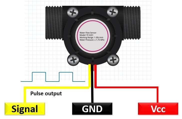
YF-S201 is a plastic body water flow sensor that has a valve, rotor, and a Hall effect sensor. They work on the Hall effect principle and output the volume and flow rate in the form of pulses on the signal pin. It has only three wires i.e. two supply wires and an output pulse wire.
Wire Configuration
Let us discuss the pinout of the YF-S201 Water Flow Sensor. The wire configuration detail in tabular is mentioned below:
| Pin Number | Pin Name | Function |
|---|---|---|
| 1 | RED | Positive supply wire |
| 2 | BLACK | Ground wire |
| 3 | YELLOW | Output Voltage wire |
How does Water Flow Sensor works?
This water flow sensor consists of a water rotor (turbine wheel) and a Hall effect sensor. Water enters through of end and leaves through the other end of the sensor. When water flows through the flow sensor, it strikes the turbine wheel and the turbine wheel rotates. The speed of the turbine wheel has a direct relation with the speed of the flow of water through the water flow sensor. On each complete rotation of the turbine wheel, a hall effect sensor also produces a pulse that appears on the signal output pin. In other words, the number of pulses that appear on the signal output pin is directly proportional to the rotational speed of the turbine.
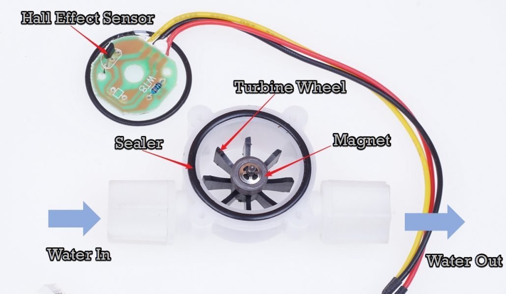
The YF-S201 is known as a Hall effect sensor because it operates on the Hall effect. In order to measure the flow or volume of the fluid, we fix the sensor between the water inlet and outlet valves. When the fluid flows through, it rotates the rotor which has a magnet attached to it. The speed interferes with the magnetic flux which is sensed by the Hall effect sensor and the sensor in returns generates an output signal proportional to the magnetic flux with every revolution that the rotor makes. As the water flow sensor is compatible with microcontrollers, we can observe the measurements on a computer serial monitor and can also display them on 16×2 LCD.
In short, for every rotation of the water rotator, the water flow sensor produces a square wave at the output pin. Hence, we can measure the water flow rate by measuring the number of pulses sensors produce in one second or in one minute. That means, we can count the number pulse which provides us information on water flow rate.
Features and Specifications
- Operational Voltage: 4.5 – 24 Volts
- Normal Voltage:5 – 18 Volts
- Maximum Current: 15 mA @ 5V
- Load Capacity: ≤10 mA Volts @ 5V
- Flow Rate Capacity: 1 -30 L/min
- Electric Strength: 1250 V/min
- Water pressure Range: ≤ 1.75 MPa
- Operational Temperature: ≤ 800C
- Operational Fluid Temperature: ≤ 1200C
- Humidity Range: 35% – 90% RH
- Insulation Resistance: ≥ 100 Mohms
Water Flow Sensor Interfacing with Arduino
This section deals with the interfacing of an Arduino microcontroller to the YF-S201 Water Flow Sensor. As discussed earlier, we need to count the output pulses of a sensor to measure the water flow rate. We can use interrupt pins of Arduino to detect a pulse. For example, whenever a pulse occurs on the output pin, the output signal goes from active low to active high state which is also known as a positive or rising edge of the pulse as shown in the figure below:
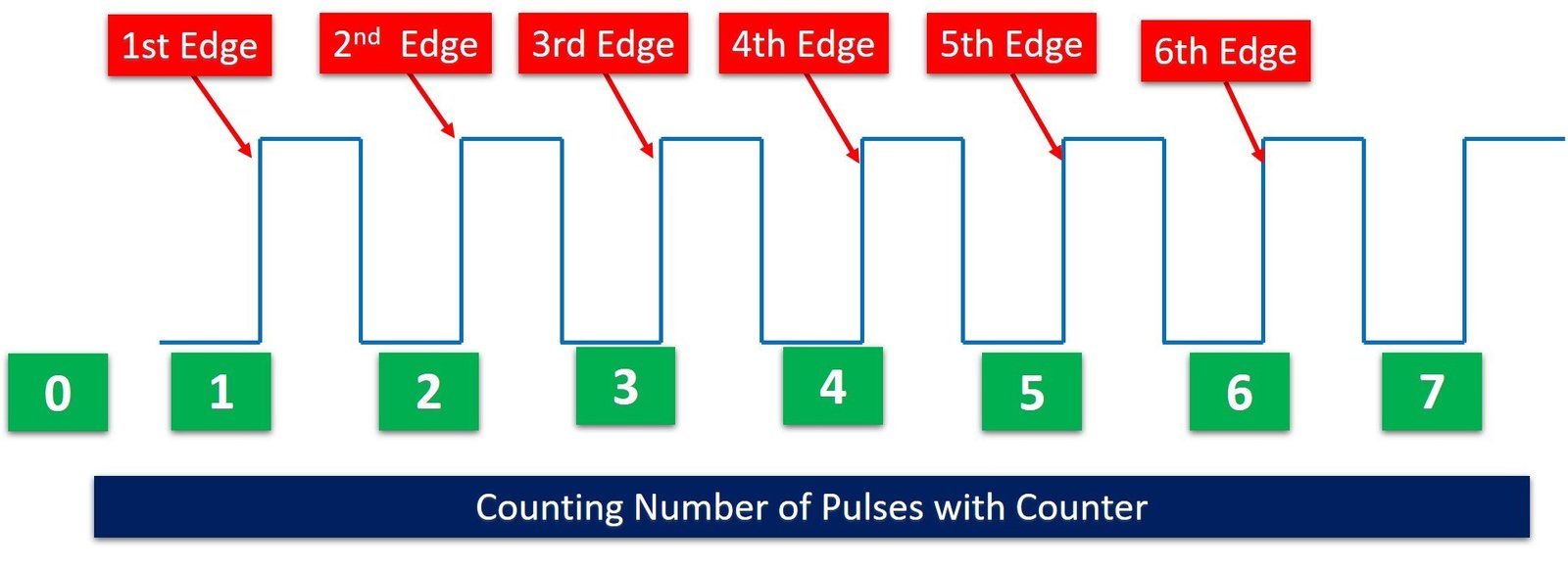
We can count these rising edges with the help of one of the interrupt pins of Arduino. Arduino provides two external interrupt pins such as Digital I/O Pins 2 and 3. We can program one of the interrupt pins in such a way that whenever a rising edge occurs, the interrupt is triggered. Hence, we can create a counter variable that will increment by one whenever the interrupt will trigger. We can start a timer for one second and count the interrupt events for one second. This will give us the number of pulses generated by the water flow sensor in one second.
For more information on Arduino interrupts, you can refer to this article:
Connection Diagram
In this example, we will use digital I/O pin 2 of Arduino as an external interrupt capture pin to count the number of pulses. Now make the connection with water flow sensor and Arduino according to this schematic diagram:
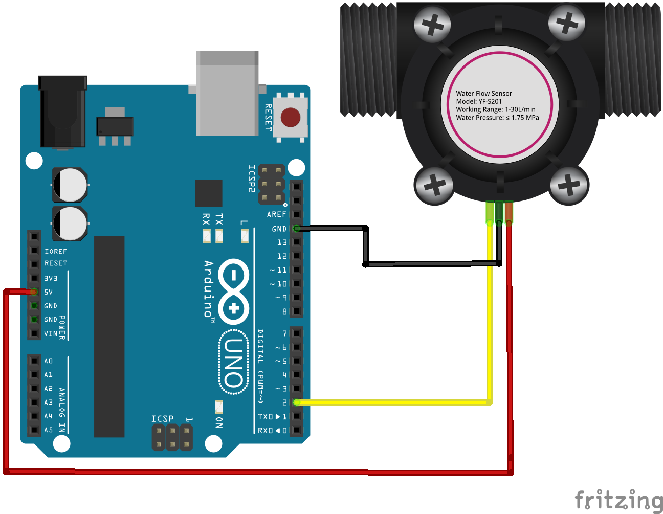
- Connect the power supply pins of the YF-S201 water sensor to the ground and 5 Volts pins of the Arduino.
- Output voltage wire(yellow) to digital pin D2 of the Arduino to detect the electric pulses.
Arduino Code
This Arduino sketch for the water flow sensor measures the water flow rate in units of a liter per hour and displays the measured value on the serial monitor of Arduino IDE.
/*YF- S201 water Flow sensor code for Arduino */
const int Output_Pin = 2;

volatile int  Pulse_Count;
unsigned int  Liter_per_hour;
unsigned long Current_Time, Loop_Time;

void setup()
{
   pinMode(Output_Pin, INPUT);
   Serial.begin(9600);
   attachInterrupt(0, Detect_Rising_Edge, RISING);

   Current_Time = millis();
   Loop_Time = Current_Time;
}

void loop ()
{
   Current_Time = millis();
   if(Current_Time >= (Loop_Time + 1000))
   {
      Loop_Time = Current_Time;
      Liter_per_hour = (Pulse_Count * 60 / 7.5);
      Pulse_Count = 0;
      Serial.print(Liter_per_hour, DEC);
      Serial.println(" Liter/hour");
   }
}
void Detect_Rising_Edge ()
{
   Pulse_Count++;
}
Now is the time to test the output of the above sketch of the water sensor. Now copy the above code to Arduino IDE and upload to your Arduino board.
After that open the serial monitor and set the baud rate to 9600. You will see the measured values on serial monitor as shown below:

The maximum portion of the Arduino code is self-explanatory except for the calculation part of the water flow rate in this line:
Liter_per_hour = (Pulse_Count * 60 / 7.5)As you know that the pulse_count variable contains the number of pulses in one second which is generated by the output pin of the water flow sensor. We multiply the Pulse_Count value with 60 to convert this measurement into one minute. Because we know that in one minute there are 60 seconds. But the question is from where this 7.5 value comes from and why we have divided Liter_per_hour with this value.
According to the datasheet of YF-S201 Water Flow Sensor, the output pulse frequency can be calculated with this equation:
Pulse frequency = 7.5 x flow rateThe above equation can also be written as:
flow rate = Pulse frequency / 7.5Here pulse frequency is the number of pulse count in one minute. Hence:
Liter_per_hour (flow rate) = (Pulse_Count * 60 / 7.5)Water Flow Sensor with Arduino and LCD
In this section, we will see how to display measured water flow rate value on 16×2 LCD. If you don’t know how to interface a 16×2 LCD with Arduino, you can check this guide:
Connection Diagram
Now make connections with Arduino, water flow sensor and 16×2 LCD according to this schematic diagram:
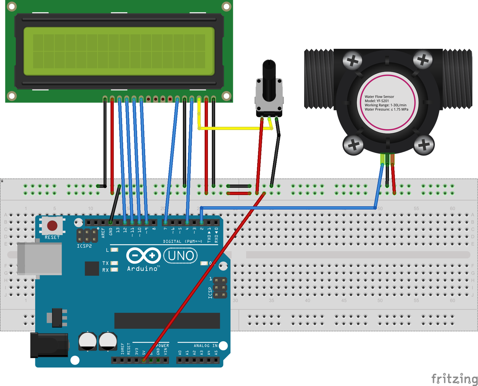
| 16X2 LCD | Arduino |
|---|---|
| D4 – D7 | 9, 10, 11, 12 |
| E | 7 |
| RS | 4 |
| VEE | POT (Middle Leg) |
| VSS | Ground |
| VDD | +5V |
| D+ | +5V |
| D- | Ground |
Connections with Arduino and water flow sensor:
| Arduino | Water Flow Sensor |
|---|---|
| D2 | Signal Output |
| 5V | VCC |
| GND | GND |
Arduino Sketch
/*YF- S201 water Flow sensor code for Arduino */
#include <LiquidCrystal.h>
LiquidCrystal lcd(4, 7, 9, 10, 11, 12);
const int Output_Pin = 2;

volatile int  Pulse_Count;
unsigned int  Liter_per_hour;
unsigned long Current_Time, Loop_Time;

void setup()
{
   pinMode(Output_Pin, INPUT);
   Serial.begin(9600);
   attachInterrupt(0, Detect_Rising_Edge, FALLING);

   Current_Time = millis();
   Loop_Time = Current_Time;
   lcd.begin(16, 2);
   lcd.clear();
   lcd.setCursor(0,0);
   lcd.print("Water Flow Meter");
   lcd.setCursor(0,1);
   lcd.print("Microcontrollers Lab");
}

void loop ()
{
   Current_Time = millis();
   if(Current_Time >= (Loop_Time + 1000))
   {
      Loop_Time = Current_Time;
      Liter_per_hour = (Pulse_Count * 60 / 7.5);
       if(Pulse_Count != 0){
      lcd.clear();
      lcd.setCursor(0,0);
      lcd.print("Rate: ");
      lcd.print(Liter_per_hour);
      lcd.print(" L/M");
      Pulse_Count = 0;
      Serial.print(Liter_per_hour, DEC);
      Serial.println(" Liter/hour");
       }
    else {
      Serial.println(" flow rate = 0 ");
      lcd.clear();
      lcd.setCursor(0,0);
      lcd.print("Rate: ");
      lcd.print( Liter_per_hour );
      lcd.print(" L/M");
    }
   }

}
void Detect_Rising_Edge ()
{
   Pulse_Count++;
}
How Code Works
Inlcude Header Files and Declare Variables
In the first part of the Arduino sketch for a water flow sensor, we include header files and perform variables declaration. The first portion of the code is to include the header files for the liquid crystal library, and declaration of the variables to store the time and output pulse count of the water flow sensor.
#include <LiquidCrystal.h>
LiquidCrystal lcd(4, 7, 9, 10, 11, 12);
const int Output_Pin = 2;

volatile int  Pulse_Count;
unsigned int  Liter_per_hour;
unsigned long Current_Time, Loop_Time;
The output voltage signal of the water flow sensor is connected to digital pin D2 which will be configured to capture rising edge interrupt. On the other hand, D4, D7, D9, D10, D11, and D12 are connected to the 16×2 LCD pins.
Detect_Rising_Edge() ISR
The Pulse_Count++ variable is used to store the pulse count. Detect_Rising_Edge() function is the interrupt function that is used to count the pulses generated by the Hall effect sensor. When an interrupt is sensed at pin D2, the Detect_Rising_Edge() routine is called and the count of pulses is incremented in Pulse_Count by one.
void Detect_Rising_Edge ()
{
   Pulse_Count++;
}
Setup Initialize Libraries
As usual for Arduino sketch, we perform initialization and configuration settings inside the setup function. First, we set the D2 pins as digital input pin using pinMode() function. After that we attach the interrupt 0 with digital pin D2 and also passes the address of callback function (Detect_Rising_Edge) which will execute every time interrupt occur due to rising edge on D2 pin.
The attachinterrupt is responsible to keep a check on the pulses. As soon as the pulse is detected, the attachinterrupt will call the subroutine and count the pulses in the flow_frequency variable. The Current_Time and Loop_Timet variables are used to keep track of time and to make sure that the code is executed every second, to calculate the volume and flow rate.
pinMode(Output_Pin, INPUT);
   Serial.begin(9600);
   attachInterrupt(0, Detect_Rising_Edge, RISING);

   Current_Time = millis();
   Loop_Time = Current_Time;
   lcd.begin(16, 2);
   lcd.clear();
   lcd.setCursor(0,0);
   lcd.print("Water Flow Meter");
   lcd.setCursor(0,1);
   lcd.print("Microcontrollers Lab");
Main Loop
The void loop will determine the flow rate by counting the frequencies or pulses every second. According to the datasheet, frequency is calculated by multiplying the flow rate by 7.5. But this code is measuring the pulses or frequencies, so we can find the flow rate by dividing the frequency by 7.5. We will further divide the flow rate to achieve the answer in liters per second. The flow rate is stored in vol and will be displayed on the LCD. The pulse counter i.e. flow_frequncy variable will reset for the next measurements and calculations.
Current_Time = millis();
   if(Current_Time >= (Loop_Time + 1000))
   {
      Loop_Time = Current_Time;
      Liter_per_hour = (Pulse_Count * 60 / 7.5);
       if(Pulse_Count != 0){
      lcd.clear();
      lcd.setCursor(0,0);
      lcd.print("Rate: ");
      lcd.print(Liter_per_hour);
      lcd.print(" L/M");
      Pulse_Count = 0;
      Serial.print(Liter_per_hour, DEC);
      Serial.println(" Liter/hour");
 }
Else Condition
If no pulse is detected the interrupt will not be called and the code flow enters the else loop. As a result, the LCD will display zero that means no water flow was sensed at a particular time.
else {
      Serial.println(" flow rate = 0 ");
      lcd.clear();
      lcd.setCursor(0,0);
      lcd.print("Rate: ");
      lcd.print( Liter_per_hour );
      lcd.print(" L/M");
    }
Demo
Upload the code on the Arduino. This code can be executed without using an LCD nut for visual purposes. Observe that when no water is flowing through the water sensor “Rate: 0 L/M and vol: 0.0 L” will be displayed on the screen as well as the serial monitor. Make some water flow through the sensor. The electric pulse will be generated due to the flow. This pulse will trigger the interrupt function which will be used by the microcontroller to calculate the volume and flow and will be displayed by the serial monitor as well as the LCD screen. After the execution, the MCU will reset the counter and is ready for the next calculations.
Applications
- Water flow measurement
- Liquid Volume measurement
- Water heaters
- Water Vending Machines
- Dispensers
- Coffee Machines
- Chemical Industries
Can u make using pic18 family microcontroller
How to make an alarm when the circulation of liquid is stopped, so that, for example, turn off a pump or a computer (if
we use water cooling of the processor)
Can you help with connecting a Flow meter to an 128×64 I2c
OLED display
bestaat er ook een interface kabel waarmee ik deze sensor op een usb poort kan aansluiten?
can i get flow sensor library for proteus please