AT24C02 is an external electrically erasable programmable Read-only memory series launched by ATMEL. AT24C02 is one of them which supports a bi-directional I2C protocol for data communication between 8 devices. This version has 2KB memory space which is arranged in the form of 8-byte pages which are 32 in total. It is a tiny, low-power device that has two operating modes depending on the input voltage. The device has 8-bytes write modes with up to one million write cycles. It comes in a space-efficient TSSOP package and is very reliable.
EEPROM applications extend from the DIY, Consumer platform to the automotive, industrial level. This tutorial is a show up of AT24C02 pinout, specifications, features, and applications.
AT24C02 Pinout
The chip is available in an 8-lead TSSOP package. The following diagram shows the pinout of the AT24C02 Two Wire Serial EEPROM:

Pin Configuration
The pin configuration in tabular are detailed as below:
| Pin Number | Pin Name | Function |
|---|---|---|
| 1 | A0 | Address0 pin |
| 2 | A1 | Address1 pin |
| 3 | A2 | Address2 pin |
| 4 | GND | Reference potential pin |
| 5 | SDA | Open-drain Serial Data line pin |
| 6 | SCL | Serial Clock line pin |
| 7 | WP | Write Protect pin |
| 8 | VCC | Positive Power supply pin |
Address pins
These are the address pins of the integrated EEPROM chip. It is capable of connecting eight different 1K/2K devices on a single bus.
I2C Interface
The device has an inter-integrated circuit for data communication between the devices and EEPROM. SCL is the clock line of the protocol while SDA is a dual directional line for transferring serial data.
Write Protect
The write protection is provided to the device to prevent any data modification. When it is connected to GND, it serves normal Write/Read operations. To enable the write protection attribute, connect it to the power supply pin.
AT24C02 Specifications
- Operating Voltage: 1.8Volts – 5.5 Volts
- Maximum Operating Voltage: 6.25Volts
- Operating Current: 5.0 mA
- Maximum Read Current: 1mA
- Maximum Standby Current: 1uA
- Output Voltage on each pin: –1.0Volts – 7.0Volts
- Data Retention Time: 100 years
- Number of Write cycles: 100 million
- Maximum Self-timed Write Cycle: 5msec
- Clock Frequency at 1.8V: 100 kHz
- Clock Frequency at 2.4V, 5V: 400 kHz
- OperatingTemperature: –55°C to +125°C
- Package Type: 8-lead,TSSOP package
Features
- The memory device has two operating modes i.e.Low-voltage and Standard-voltage Operation.
- This version of the AT24C0 series is organized as 32 pages of 8 bytes each.
- The 2K allocates each word with an 8-bit data word address and stores them in the memory.
- The device supports Two-wire Serial Interface for read/write operation.
- It has a Schmitt Trigger to filter the inputs to minimize unwanted noise.
- Data Transfer Protocol in AT24C02 is dual-directional.
- It is embedded with hardware wire protection to avoid mechanical data loss.
- AT24C02 allows Partial Page Write and is a highly durable device.
Block Diagram
The block diagram to understand the internal circuitry of the EEPROM is as shown:
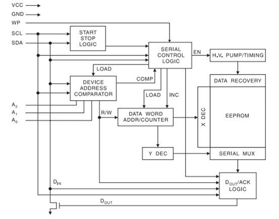
How does the AT24C02 EEPROM work?
AT24C02 EEPROM works on start-stop conditions. The EEPROM gets ready to read or write when both the clock line and the data line change from high to low state. The EEPROM acquires the peripheral device address, the byte address, and the information which is to be stored. After the transmission, the operation is terminated. This is determined by the stop condition i.e both the lines of the I2C interface transits from low to high state. You can learn more about I2C communication format in the following article:
Interfacing EEPROM with Microcontroller
AT24C02 can be interfaced easily with any microcontroller unit with the I2C Bus protocol. The interfacing of EEPROM is done by connecting the power supply of both the modules and interconnecting SDA and SCL of the electrically erasable programmable ROM to the I2C lines of the Arduino. Also, use pull-up resistors if the MCU does not have internally integrated pull-up resistors.
Interfacing EEPROM with Arduino UNO
In this section, we will see an example to interface AT24C02 EEPROM with Arduino. Almost all Arduino development boards have at least one I2C port. Similarly, Arduino Uno also has one I2C port which we can use to write and read data from this EEPROM chip. Connect the Arduino and EEPROM as shown in the interfacing diagram below:

To enable wiring protection and stop the writing, connect WP to VCC. We are using a single EEPROM, so we won’t be using the address pins.
| Arduino UNO | AT24C02 EEPROM |
|---|---|
| 5V | VCC |
| GND | GND |
| A4 | SDA |
| A5 | SCL |
| WP | GND |
Arduino Code
#include <Wire.h>

#define ADDR_Ax 0b000 //A2, A1, A0
#define ADDR (0b1010 << 3) + ADDR_Ax

void setup() {
  // put your setup code here, to run once:
  Serial.begin(9600);
  Wire.begin();
  writeI2CByte(0, 1);
  Serial.println(readI2CByte(0));
}

void loop() {
  // put your main code here, to run repeatedly:

}

void writeI2CByte(byte data_addr, byte data){
  Wire.beginTransmission(ADDR);
  Wire.write(data_addr);
  Wire.write(data);
  Wire.endTransmission();
}

byte readI2CByte(byte data_addr){
  byte data = NULL;
  Wire.beginTransmission(ADDR);
  Wire.write(data_addr);
  Wire.endTransmission();
  Wire.requestFrom(ADDR, 1); //retrieve 1 returned byte
  delay(1);
  if(Wire.available()){
    data = Wire.read();
  }
  return data;
}
How does the code work?
The code depicts the writing and reading of the data.
First, the library “Wire.h” is included to perform read/write functions. Next, the 8-bit device address is sent to communicate the data. The last bit of the address determines whether the device reads or writes in the EEPROM.
#include <Wire.h>

#define ADDR_Ax 0b000 //A2, A1, A0
#define ADDR (0b1010 << 3) + ADDR_Ax

void setup() {
  // put your setup code here, to run once:
  Serial.begin(9600);
  Wire.begin();
  writeI2CByte(0, 1);
  Serial.println(readI2CByte(0));
}
To write the data the last bit should be 0. It is followed by the specified memory data address and the data to be written. The data is now stored at the location.
void writeI2CByte(byte data_addr, byte data){
  Wire.beginTransmission(ADDR);
  Wire.write(data_addr);
  Wire.write(data);
  Wire.endTransmission();
}
To read the data from that location, the request is made through “Wire.requestFrom” which consists of the device address with the last bit as1 to read the data, and the second argument is kept 1 which means the function will return one byte of data. The function “Wire.available” will check the memory address and will return the data stored in the location. It will be displayed on the Serial monitor.
byte readI2CByte(byte data_addr){
  byte data = NULL;
  Wire.beginTransmission(ADDR);
  Wire.write(data_addr);
  Wire.endTransmission();
  Wire.requestFrom(ADDR, 1); //retrieve 1 returned byte
  delay(1);
  if(Wire.available()){
    data = Wire.read();
  }
  return data;
}
Alternate Options
- DS2431+ One Wire EEPROM
- 24LCxxx EEPROM
- AT28C64B 64 Kilobit EEPROM
Applications
- Communication systems
- Automobiles
- Data Storage
- Consumer electronics
- Industrial applications
- Testing devices
2D Diagram

Related Articles: