Relay module for Arduino is one of the most powerful application for Arduino as it can be used to control both A.C and D.C devices by simply controlling the relay by giving 5V. A relay is basically a switch which is operated electrically by electromagnet. A relay can be used to control high voltage electronic devices such as motors and as well as low voltage electronic devices such as a light bulb or a fan.
Relays works on the principle of electromagnetism. When the electricity is provided to the relay coil then it acts like a magnet and changes the state of the switch. The part which powers the relay module is completely isolated from the part which turns ON or OFF. This is why we can control a 220V appliance by simply controlling it using the 5V Arduino. you should also read getting started projects of arduino.
Recommended Components
The following components are used in this project or are helpful for building it with the Arduino.
| Component | How it’s used in this project | Buy on Amazon |
|---|---|---|
| Arduino Uno R3 | The main microcontroller board that runs the project code and controls all connected components. | Check Price |
| Relay Module | Lets the Arduino switch a high-voltage or high-current load on and off. | Check Price |
| Breadboard | Lets you build and prototype the circuit without soldering. | Check Price |
| Jumper Wires | Used to make the connections between the Arduino, breadboard and the modules. | Check Price |
As an Amazon Associate we earn from qualifying purchases. Prices and availability are accurate as of the date/time indicated and are subject to change.
Relay Module
There many types of relay modules available like 1 relay, 2 relay, 5 relay and 8 relay but we are using the 4 relay Arduino module. Once you will understand this then you can use all other types.

Relay Module Pinout
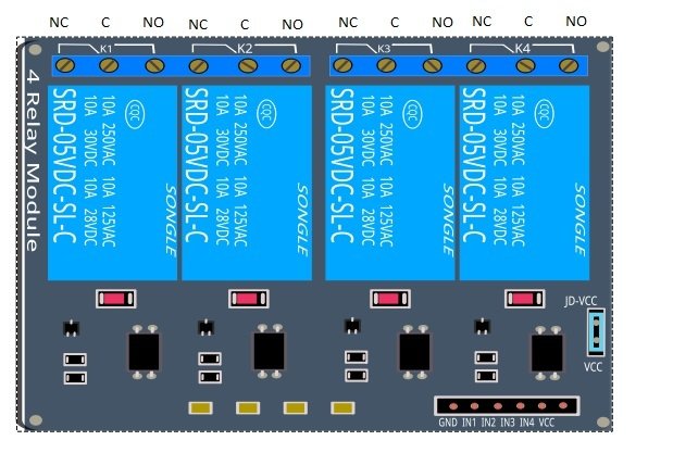
Input Connections of relay module
- I recommend you to learn how to use digital output of arduino microcontroller. Before reading this article further.
- Logic GND: This will be connected to GND on your Arduino.
Input 1 (IN 1): This will be connected to digital pin on your Arduino, or leave it unconnected if - you do not want to use this channel.
- Input2 (IN 2): This will be connected to the digital pin on your Arduino, or leave it unconnected if you do not want to use this channel.
- Input3 (IN 3): This will be connected to the digital pin on your Arduino, or leave it unconnected if you do not want to use this channel.
- Input4 (IN 4): This will be connected to the digital pin on your Arduino, or leave it unconnected if you do not want to use this channel.
- Logic VCC: This will be connected to the 5v pin of the Arduino o power the 4 relay module.
- You can also power the 4 relay module using the external power by giving voltage from 5 to 24V DC.
Output Connections of relay module
- you may also like to read Xbee interfacing with arduino
Before getting into the output connections of the relay, we have to understand the NO, COM and NC connections. - COM (Common connection): The COM is the center terminal of the relay and it is used in both (Normally open and normally closed) connections.
- NO (Normally open): This act like a switch. In normally open connection, there will be no contact between COM and NO, since it is normally open. But when we will activate the relay module, then it will get connected to the COM and will supply power to the load, which will power up the light. Thus the circuit will initially be in open state until we trigger the state.
- NC (Normally closed): its behavior is opposite to the normally open connection. It always remains in contact with COM, even when relay module is not powered. When we will trigger the relay module then it will open the circuit, so the connection is lost.
- We will use the normally open connection. When you will use the relays in NO (Normally Open) connection and you set the corresponding IN pin to LOW, then the power will flow from the COM connector and out of the normally open connector powering your device.
- Relay 1 (K1): Connect one end of the load to the COM and the other end to the NO.
- Connections for the K2, K3 and K4 are the same.
relay module interfacing with arduino
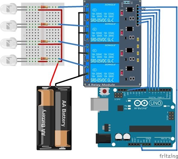
The connection of 4 relay module to an Arduino is very easy and allows you to control many devices through Arduino (both A.C and D.C). In this example we will connect a simple load such as a led at the output of the relay and will control it by using the Arduino. First connect the 5v of the Arduino to the VCC of the 4 relay module and the ground of the Arduino to the ground of the 4 relay module. Then we will have to connect the communication pins IN1, IN2, IN3, and IN4 to the Arduino data pins 7, 6, 5, and 4.
We will use a 3v battery to power the Led’s. So we have connected the positive of the battery to the positive side of the led’s and then we have connected the negative side to the com of each relay and the NO to the negative side of the led’s.
Components Required for relay module
- Arduino Uno (You can use any other type)
- 4 Relay module
- 3v Battery
- Led’s
- 220 ohm resistors
- Breadboard
Video lecture on Arduino with relay module
Code of relay module interfacing with microcontroller
The following code is for the basic 4 Relay Module connection to the Arduino. Each relay will turn on for 5 seconds and then will turn off. You will hear the click sound as there state changes from OFF to ON or from ON to OFF. You will also see the Red LED on the 4 Relay board light up when the relay will on. Necessary comments are made in the code for better understanding. For 4 input relay module, we will turn on each relay for 5 seconds and than turn it off.
 #define RELAY1 7 //Defining the pin 7 of the Arduino for the 4 relay module
 #define RELAY2 6 //Defining the pin 6 of the Arduino for the 4 relay module
 #define RELAY3 5 //Defining the pin 5 of the Arduino for the 4 relay module
 #define RELAY4 4 //Defining the pin 4 of the Arduino for the 4 relay module

void setup()
 {
 pinMode(RELAY1, OUTPUT); //Defining the pin 7 of the Arduino as output
 pinMode(RELAY2, OUTPUT); //Defining the pin 6 of the Arduino as output
 pinMode(RELAY3, OUTPUT); //Defining the pin 5 of the Arduino as output
 pinMode(RELAY4, OUTPUT); //Defining the pin 4 of the Arduino as output
 }

void loop()
 {
 digitalWrite(RELAY1,LOW); // This will Turn ON the relay 1
 delay(5000); // Wait for 5 seconds
 digitalWrite(RELAY1,HIGH); // This will Turn the Relay Off

digitalWrite(RELAY2,LOW); // This will Turn ON the relay
 delay(5000); // Wait for 5 seconds
 digitalWrite(RELAY2,HIGH); // This will Turn the Relay Off

digitalWrite(RELAY3,LOW); // This will Turn ON the relay
 delay(5000); // Wait for 5 seconds
 digitalWrite(RELAY3,HIGH); // This will Turn the Relay Off

digitalWrite(RELAY4,LOW); // This will Turn ON the relay
 delay(5000); // Wait for 5 seconds
 digitalWrite(RELAY4,HIGH); // This will Turn the Relay Off
 }
Other Relay tutorials:
Thanks sir
Good jobe
thanks for the code working well
Hi i’m trying to control the light using arduino uno with two channel relay board for automatic light intensity system using LDR and but the relay was operating reverse functioning but i don’t know how to solve the problem.
Thank you brilliant explanation. You have just saved me hours of head scratching.
Dear sir,
Good morning ,
Good explanation. Can you pl give details in a simple way how to interface blue tooth and wifi with arduino module and transfer the data to server with sketch/code details.
Thanking you.
Regards
U.R.Padmanabhan