This is the third tutorial in a series of tutorials on Arduino. In the last tutorial, we have seen. How to use Arduino digital pins as an output. In this tutorial, we will see how to use digital pins of Arduino as input but you should have a concept of using digital pins of Arduino as an output. How to use push button with Arduino UNO R3, In this article I have discussed push button use with Arduino UNO R3. How to use digital pins of Arduino as an input pin.

To demonstrate the use of digital pins as an input, push-button is used to control two LEDs connected with digital input/output pins of Arduino. If you don’t know how to use Arduino pins as an output. Go through the following tutorial :
How to use Arduino UNO R3 digital pins as an output
Recommended Components
The following components are used in this project or are helpful for building it with the Arduino.
| Component | How it’s used in this project | Buy on Amazon |
|---|---|---|
| Arduino Uno R3 | Reads the push button state on a digital input pin and runs the sketch. | Check Price |
| Tactile push button | The momentary switch the user presses to send a digital input to the Arduino – the main component of this project. | Check Price |
| Breadboard | Holds the push button and pull-down/up resistor for solderless prototyping. | Check Price |
| Jumper Wires | Connect the push button to the Arduino digital input, 5V and GND. | Check Price |
As an Amazon Associate we earn from qualifying purchases. Prices and availability are accurate as of the date/time indicated and are subject to change.
Reading Digital Inputs of Arduino
To use GPIO pins of Arduino to read digital input, we use the pinMode() function of Arduino. The pinMode() routine is used to define GPIO pins as a digital output pin like this:
pinMode(GPIO_Pin,INPUT);For example, if you want to declare GPIO_0 of Arduino as a digital input pin, use above function like this:
pinMode(0,INPUT);After configuring GPIO pin as a digital output pin, we can read the state of input pin using digitalWrite() function:
int state;
state = digitalRead(GPIO_Pin);
This digitalWrite() accepts one input argument that is the pin number of whose state you want to know. This function returns logic high or low depending on the state of the digital input pin.
Schematic Diagram
Two LEDs are connected with pin numbers 1 and 2 of the Arduino board. the push button is connected with pin number 0 of the Arduino board.
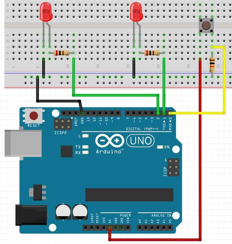
Push Button Interfacing
Push button is basically used to control two LEDs or to turn on/off two LEDs. when the push button is pressed. Both LEDs glow and when a push button is unpressed, LEDs remains turn off. Two resistors are connected in series with both LEDS as a current limiting resistor.
Pull Down Resistor
Push-button one side is connected with 5-volt source and the other side is connected with ground through 10k ohm resistor. When the push button is not pressed, a logic low is used as input for pin 0 and when the push button is pressed, logic high is used as an input of pin 0.
Note: 10k Ohm resistor with push-button is used as a pull-down resistor. It will make the state of digital input logic low as soon as we release the push button, otherwise, a floating state will appear on the digital input zero.
Arduino also has an internal pull-down resistor. In the later section of this tutorial, we will see how to use the push button by using the internal pull-up resistor of Arduino. It will eliminate the need for an external resistor.
Circuit diagrams of both states are shown below Simulation diagram when the push button is not pressed:

This diagram shows the output when the push button is pressed. As you can see both LEDs are on.

Arduino Sketch
The code of the above circuit is given below. Copy this code to Arduino software.
int buttonStatus; // Variable declare to store status of digitalWrite
 void setup()
{

  pinMode(1, OUTPUT);
  pinMode(2, OUTPUT);
  pinMode(0, INPUT);
 }

void loop()
 {

 buttonStatus = digitalRead(0);
  if (buttonStatus == HIGH)
  {
  digitalWrite(1, HIGH);
  digitalWrite(2, HIGH);
  }
  else
  {

 digitalWrite(1, LOW);
  digitalWrite(2, LOW);
  }
 }
How Code Works?
To understand the programming of push button use with Arduino, First, you need to know the input function and its use. Explanation of the input function is given below :
pinMode(pin number, INPUT): I have already discussed pinMode function use in LED blinking with Arduino UNO R3. The same function is used to declare pin as an input pin. Where INPUT argument is used to declare the specified pin number as an input pin. For example pinMode(0, INPUT) function declare pin 0 as a input pin.
digitalRead(pin number): digitalRead function is used to read status of input pin either pin is at logic level high or logic level low. The output of this function is stored in another variable which can be used to perform other functions according to your application.
digitalWrite(pin number, HIGH/LOW): digitalWrite function is used to write or output at specified pin number either output is logic high or logic low.
First, you define an integer variable that will be used to store the state of push button.
int buttonStatus; // Variable declare to store status of digitalWrite()Inside the setup function, we configure digital pin 1 and 2 as output pins using pinMode() routine. Similarly, we declare digital pin zero as a input pin.
 void setup()
{
  pinMode(1, OUTPUT);
  pinMode(2, OUTPUT);
  pinMode(0, INPUT);
 }
As you know that in Arduino sketch, everything that executes again and again place inside the loop function. Inside the loop(), first we check the state of pin zero using digitalRead() function and save the state of pin in “buttonstate” variable.
After that if condition is used to check the state “buttonstate” variable. If condition is true, digitalWrite() make digital output pins active high and otherwise these output pins remains active low.
void loop()
 {

 buttonStatus = digitalRead(0);
// if button pressed execute next instructions
// other execute instructions under else block
  if (buttonStatus == HIGH)
  {
  digitalWrite(1, HIGH); // Set pin_1 active high
  digitalWrite(2, HIGH); //// Set pin_2 active high
  }
  else
  {

 digitalWrite(1, LOW); // Set pin_1 active low
  digitalWrite(2, LOW); // Set pin_2 active low
  }
 }
Video Demo
Push Button Interfacing with Internal Pull-Up resistor
In the last example, we have used a external resistor with a push button. But, Arduino also offers internal Pull-Up feature. We can configure internal Pull-Up by using pinMode().
This line will enable the internal pull-up resistor of arduino and we can directly interface a push button with Arduino.
// Make pin 2 digital input with internal pull-up resistor enabaled
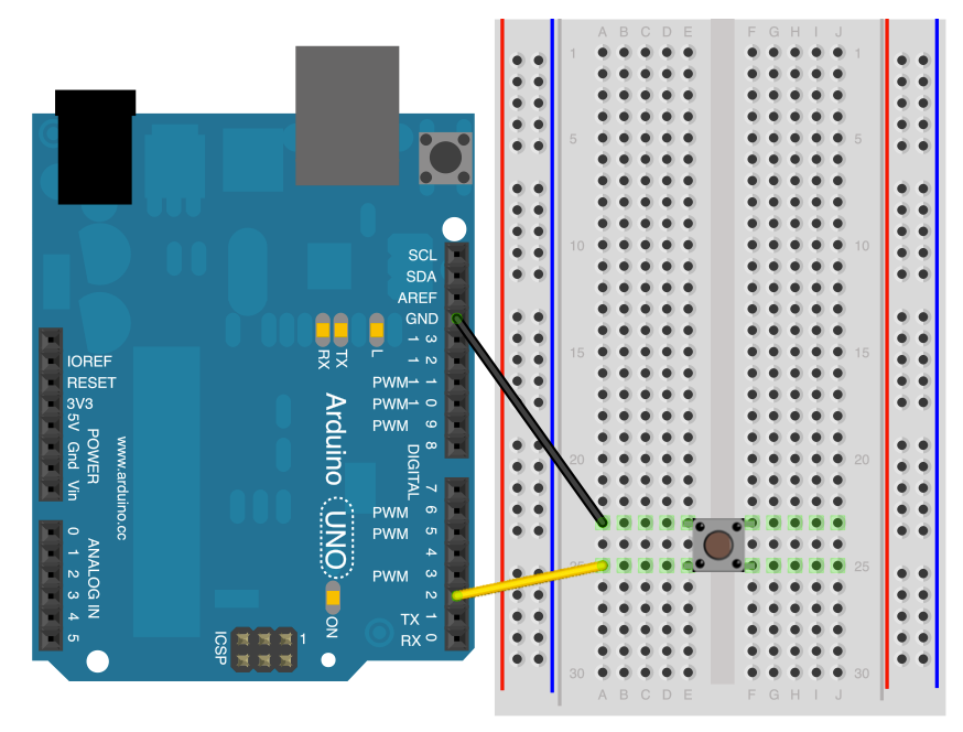
pinMode(2,INPUT_PULLUP); Schematic Diagram
In this diagram, we connected only a push button with digital pin 2 of Arduino and we will use on board LED which is connected with pin 13 of Arduino.
Arduino Sketch
This is an example code to control LED with push button and internal pull-up resistor.
void setup()
{
  pinMode(13,OUTPUT);
  pinMode(2,INPUT_PULLUP);// put your setup code here, to run once:
}

void loop()
{
  if(digitalRead(2)==LOW)
  {
  digitalWrite(13,HIGH);
  }
  else
  digitalWrite(13,LOW);
}
Other Tutorials:
- LCD Interfacing Arduino
- Keypad Interfacing Arduino
- Analog Voltage Read Arduino
- Arduino Interrupts
- Arduino Send Messages from Android to LCD with MIT App Inventor
- Arduino Watchdog Timer Tutorial with Example
- MAX30102 Pulse Oximeter and Heart Rate Sensor with Arduino
- Control Stepper Motor with A4988 Driver Module and Arduino