In this user guide, we will learn to build an Android App using MIT App Inventor and display temperature readings acquired from DS18B20 sensor with Arduino. The transmission of sensor data will be through the HC-05 Bluetooth module.
Our Android application will display sensor readings on our smartphones. The sensor readings could be accessed anywhere and anytime conveniently. Any appropriate sensor can be used such as DHT22, BME680, LM35, and MPU6050 but for this article, we will use a DS18B20 sensor which is used to measure temperature. We will use Arduino IDE to program our Arduino which will be connected to a DS18B20 sensor and the HC-05 module. Additionally, we will send the sensor readings in real-time using Bluetooth through our app which will be built in MIT App Inventor.
Project Overview

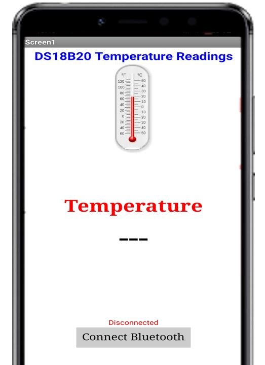
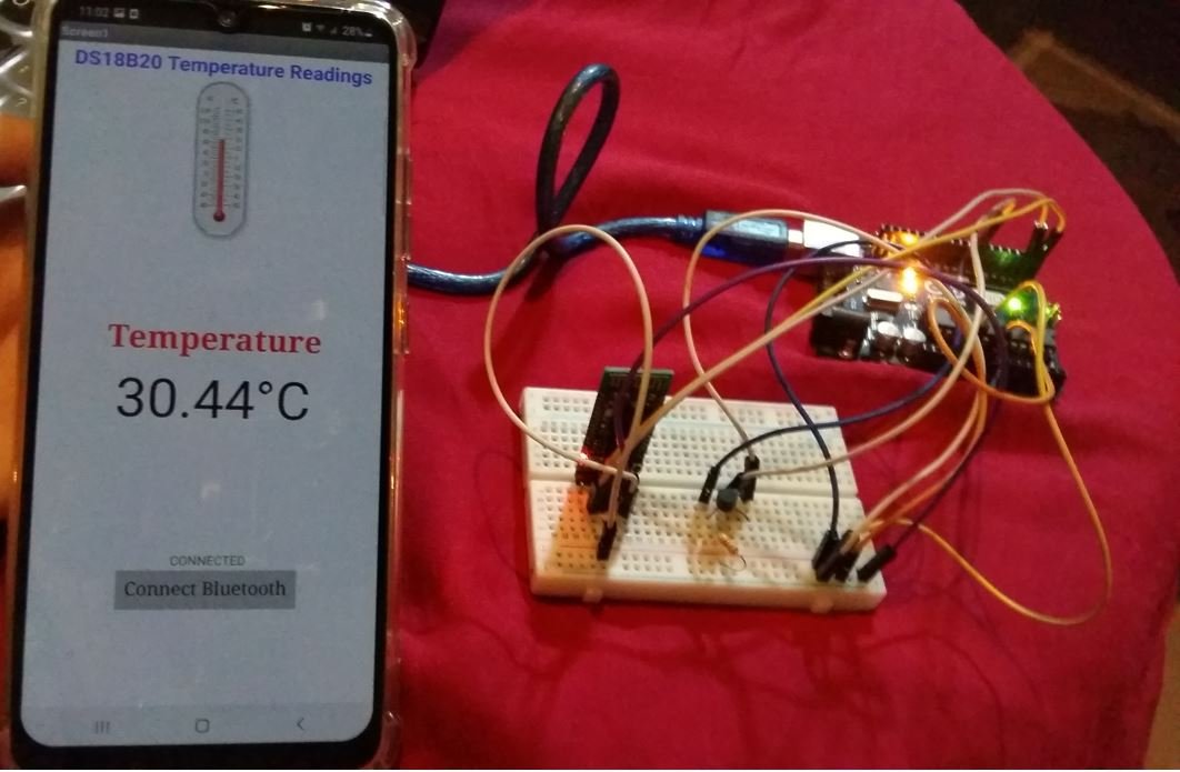
We will create an Arduino IoT app through HC-05 and MIT App Inventor. The heading of the app will consist of “DS18B20 Temperature Readings” followed by an image of a thermometer. Then a label for ‘Temperature’ and its reading with appropriate units. Another label saying Bluetooth is connected or disconnected and beneath that a button saying ‘Connect Bluetooth’ that opens a List picker.
We aim to build an application that will display sensor readings obtained from DS18B20 connected with Arduino programmed in Arduino IDE. This transmission of data from the module to the application will occur via Bluetooth. The reading will automatically update to new values in real-time when the IoT app receives them.
We will require the following for our project:
Hardware Required:
- Arduino UNO
- DS18B20 Sensor
- 4.7k ohm resistor
- HC-05 Module
- Connecting Wires
- Breadboard
Software Required:
- Arduino IDE
- MIT App Inventor
- Android Smartphone with MIT AI2 Companion installed
DS18B20 Introduction
It is a temperature sensor that is single wire programmable in nature. It is widely used to measure the temperature of chemical solutions and substances which are present in a hard environment. One of the advantages of using this sensor is that we only require a single pin of our Arduino board to get temperature samples. Therefore, it is extremely convenient to use with the microcontroller as we can use multiple DS18B20 temperature sensors by using only one pin on Arduino.
The table below shows some key characteristics of the ds18b120 sensor.
| Feature | Value |
|---|---|
| Operating Voltage | 3-5V |
| Temperature Range | -55°C to +125°C |
| Accuracy | ±0.5°C |
| Output Resolution | 9-12 bit |
Pinout Diagram
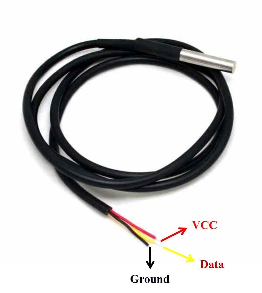
A waterproof version of this sensor is also available in the market. The following figures show the pinout of the DS18B20 sensors.
The following diagram shows the pinout of the normal DS18B20 temperature sensor.
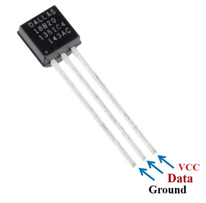
The table below lists the pin configurations:
| Pin | Description |
|---|---|
| VCC | This is the pin that powers up the sensor. It is 3.3V for ESP boards. |
| Data | This pin gives the temperature reading. |
| Ground | This pin is connected with the ground |
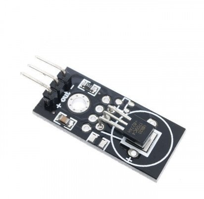
This temperature sensor also comes in a single package module which contains a sensor and a pull-up resistor. If you are using a module, you do not need to connect an external 4.7K ohm resistor. This is because the module already has an onboard pull-up resistor.
You can have a look at articles related to DS18B20 by accessing the links below:
- MicroPython: DS18B20 Web Server with ESP32/ESP8266(Weather Station)
- DS18B20 Temperature Module interfacing with arduino
Installing DS18B20 Library in Arduino IDE
The DS18B20 temperature sensor provides an output on a 1-Wire protocol which requires a complex Arduino sketch to be written from the scratch. Instead of reinventing the wheel, we can use the Dallas Arduino library. We can use simple functions to get temperature samples from the DS18B20 sensor with this library.
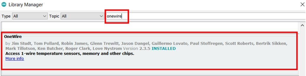
To use the Dallas DS18B20 sensor we will have to install two libraries.
- OneWire library
- DallasTemperature library
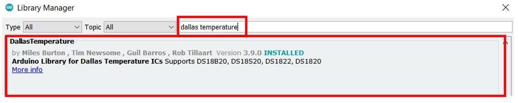
Follow the steps below to successfully install them. We will use the Library Manager in our Arduino IDE to install the latest versions of the libraries. Open your Arduino IDE and go to Sketch > Include Libraries > Manage Libraries. Type each library name in the search bar and install them both.
After installation of the libraries, restart your IDE.
Interfacing DS18B20 sensor and HC-05 module with Arduino board

The connection of DS18B20 with the Arduino board is very simple. The DS18B20 sensor can be powered in two different modes.
Normal Mode: The sensor is powered through an external source through the VDD pin and 4.7K ohm pull-up resistor.
Parasite Mode: The sensor obtains power from its own data line. Hence, no external power supply is required.
For this project, we will power the sensor in the normal mode. Thus, we have to connect the VCC terminal of the DS1B80 sensor with 5V, ground with the ground (common ground), and the data pin of the sensor with an appropriate digital pin of Arduino via a pull-up resistor. For this tutorial, we will use the D7 pin of Arduino for 1-wire protocol communication.
Follow the connections below for HC-05 module with Arduino:
- Bluetooth Tx with Arduino UNO Rx (D0)
- Bluetooth Rx with Arduino UNO Tx (D1)
- Bluetooth VCC with Arduino UNO +5V
- Bluetooth GND with Arduino UNO GND

NOTE: Make sure you plug out the Tx and Rx pins out of Arduino before uploading the program. After uploading the program connect them back. Otherwise, you can get an error.
You may also like to read:
Arduino Sketch to Send Sensor Data through Serial Port
Open your Arduino IDE and go to File > New to open a new file. Copy the code given below in that file.
This sketch obtains the current temperature reading from the DS18B20 sensor after every 5 seconds and sends it to the Bluetooth module via serial port. These temperature readings will then be fetched by the Android App from the Bluetooth module.
#include <OneWire.h>
#include <DallasTemperature.h>

const int SensorDataPin = 7;

OneWire oneWire(SensorDataPin);
DallasTemperature sensors(&oneWire);

unsigned long previousMillis = 0;
const long interval = 5000;

void setup() {
  sensors.begin();
  Serial.begin(9600);
}

void loop() {
  unsigned long currentMillis = millis();
  if (currentMillis - previousMillis >= interval) {
    previousMillis = currentMillis;
    sensors.requestTemperatures();
    float temp = sensors.getTempCByIndex(0);
    Serial.print(temp);
  }
}
How the Code Works?
Firstly, we will include the necessary libraries. For this project, we are using two of them. As we have to connect our Arduino to the DS18B20 sensor thus we will require the following libraries: OneWire.h and DallasTemperature.h. These were the ones which we previously installed.
#include <OneWire.h>
#include <DallasTemperature.h>
Secondly, we will create a variable to store the digital pin D7 through which the sensor’s data pin is connected. We have used GPIO7 in this example.
const int SensorDataPin = 7; We will require the following instances as well to access the temperature readings. First, we will create a oneWire instance and use the SensorDataPin as an argument inside it. Then we will call the DallasTemperature sensor and pass the oneWire reference which we created above as an argument inside it.
OneWire oneWire(SensorDataPin);
DallasTemperature sensors(&oneWire);
setup() function
Inside the setup() function, we will open a serial connection at a baud rate of 9600. Moreover, we will call sensors.begin() to initialize the DS18B20 sensor as well.
void setup() {
  sensors.begin();
  Serial.begin(9600);
}
loop() function
In the infinite loop() function, we will obtain the temperature reading from the sensor after every 5 seconds. After every 5 seconds, we will call the requestTemperatures() method. Then we will use the getTempCByIndex() function to retrieve the temperature in degree Celsius. Notice that we are passing 0 as a parameter inside the function. This is because we are using a single DS18B20 sensor. When using multiple sensors this value will increment for each additional sensor. Finally, we send the sensor data to via the serial.
void loop() {
  unsigned long currentMillis = millis();
  if (currentMillis - previousMillis >= interval) {
    previousMillis = currentMillis;
    sensors.requestTemperatures();
    float temp = sensors.getTempCByIndex(0);
    Serial.print(temp);
  }
}
Building App with MIT APP Inventor to Display Sensor Data
MIT App Inventor is an incredible web application that helps users build interesting Android applications. It is a block-based programming tool through which users can create fully functional apps for Android devices such as smartphones, tablets e.tc. Often termed beginner-friendly, even people with no prior experience in programming can easily learn how to use this application efficiently. We will use this tool to build our Arduino sensor-based app as well.
Steps to Create Android App
Go to the following website: and click the ‘Create Apps!’ button.

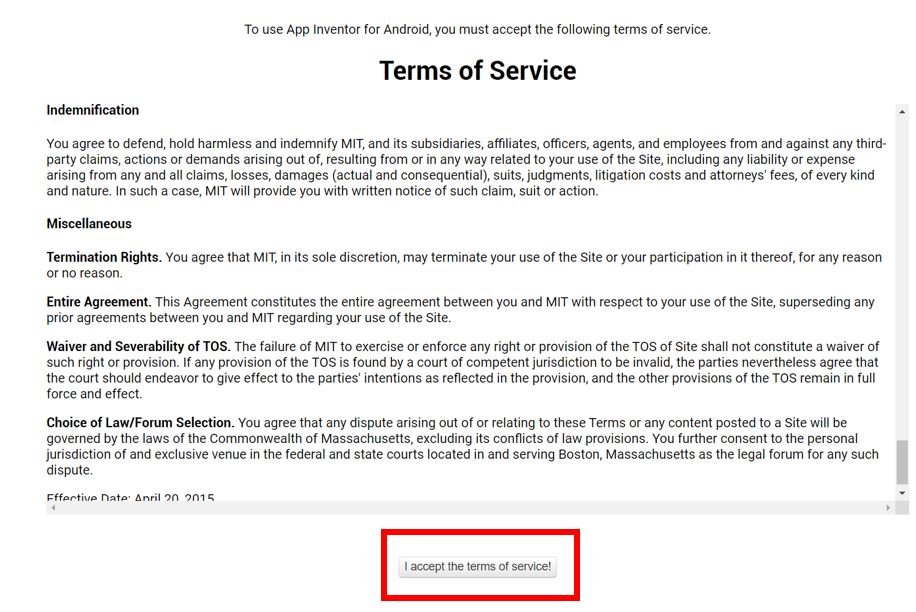
You will be redirected to a new window where you will be asked to sign in with your email account. After signing in you will have to accept the terms as shown below.
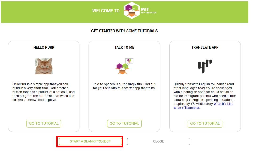
You will receive a welcome message. You can visit the link to get more information on how to install the inventor on your smartphone. Press ‘Continue’ to proceed. If you want, you can have a look at the tutorials being specified. Otherwise, go to ‘Start a blank project’ to start your app invention.
You will be asked to specify your project name. Choose an appropriate name. Click ‘ok.’

The following page will open. It is known as the Designer. This is where we will design the user interface of our app. We can add text, buttons, images and various other functionalities to our app by dragging and dropping components from the palette to the viewer. Then we will set their attributes through the ‘Properties’ column.

Creating User Interface
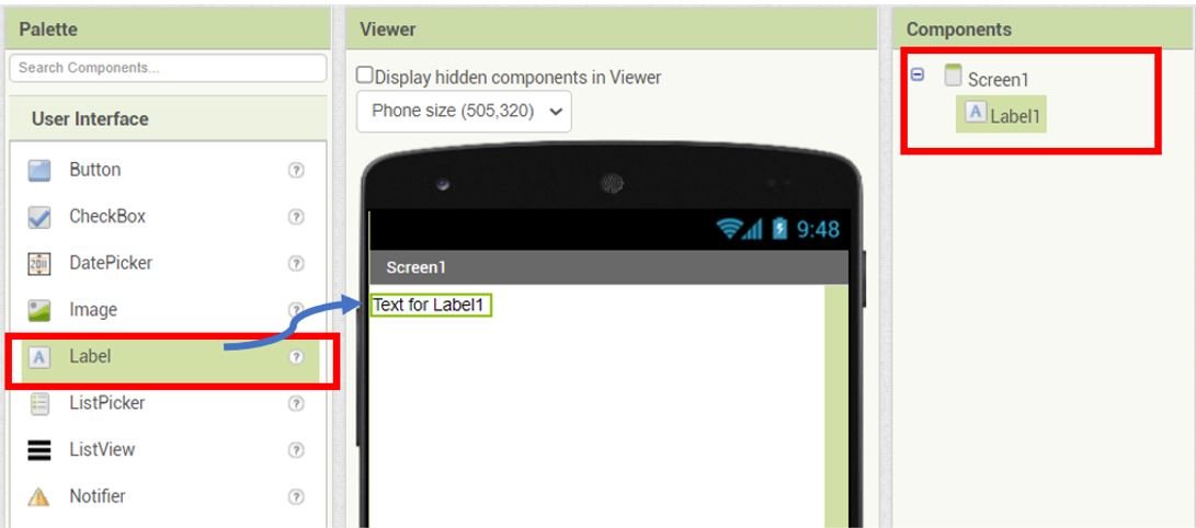
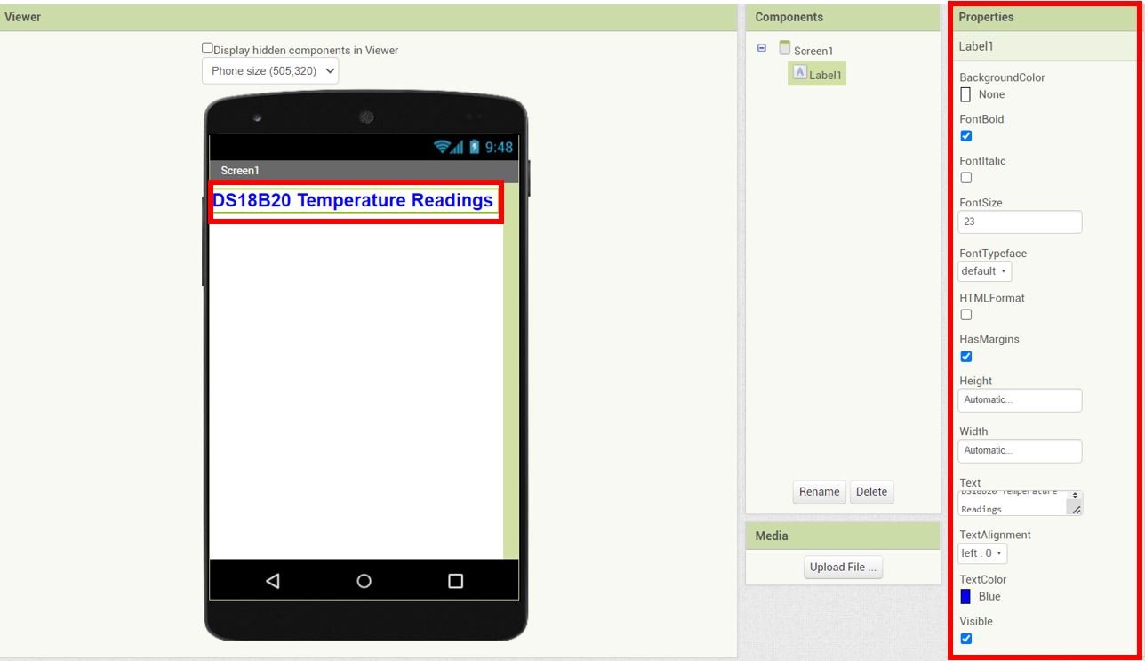
Firstly, we will add a heading for our app. Go to Palette > User Interface and head over to ‘Label.’ Now click and drag the label. Drop it on the Viewer side. Now you will be able to view it in the viewer as well as in the components list.
Head over to the ‘Properties’ to change the text, font size and colour. The label will automatically update in the viewer. Keep in mind the viewer will show you the final look of your app which will appear on your smartphone.
You can change the properties of the label to incorporate your preferred spacing dimension by changing the width and height of the label.
Add Thermometer Image
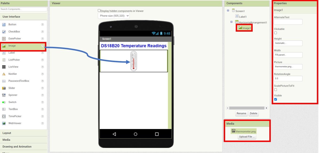
Next, we will add a block for the thermometer image. Go to Palette > Layout > HorizontalArrangement. Click and drag HorizontalArrangement and drop it in the Viewer.

Go to the ‘Properties’ and set AlignHorizontal to Centre : 3 and AlignVertical to Centre : 2. We have set the height to 25% and width to fill parent.

To insert an image, go to Media and upload the file. Next, go to User Interface > Image and set its Properties as follows:
Height: Automatic
Width: Fill parent
Picture: thermometer.png (the image file that you a uploaded in media)
Add Temperature Label and Readings
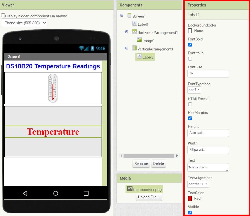
Next, we will add a block for the temperature label and readings. Go to Palette > Layout > VerticalArrangement. Click and drag VerticalArrangement and drop it in the Viewer. Set the Properties of the VerticalArrangement as follows:
Align Horizontal: Centre : 3
Align Vertical: Centre : 2
Height: 40 percent
Width: Fill parent

Now go to Palette > User Interface and head over to ‘Label.’ Now click and drag the label. Drop it on the Viewer side. Head over to the ‘Properties’ to change the text, font, font size and color. We have set the FontSize to 36, FontTypeface to serif, Height to Automatic, Width to Fill parent, Text to Temperature, TextAlignment to center : 1 and TextColor to red.
Add another label for temperature readings, and rename it as ‘Temperature_Reading’ using the rename button found in the Components section.
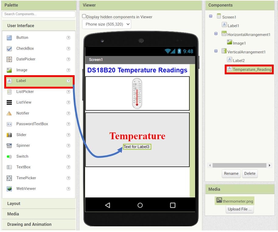
Head over to the ‘Properties’ to change the text, font, font size and color of the Temperature_Reading label. We have set the FontSize to 60, FontTypeface to Default, Height to Automatic, Width to Fill parent, Text to —, TextAlignment to center : 1 and TextColor to Default.

Add Bluetooth Connection Button
Go to Palette > Layout > VerticalArrangement. Click and drag VerticalArrangement and drop it in the Viewer.
Go to the ‘Properties’ and set them as follows:
AlignHorizontal: Center : 3
AlignVertical: Center : 2
BackgroundColor: None
Height: 20 percent
Width: Fill parent

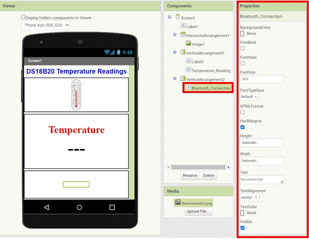
Add a label and rename it as ‘Bluetooth_Connection’ using the rename button found in the Components section.
Head over to the ‘Properties’ to change the text, font, font size and color of the this label. We have set the FontSize to 14, FontTypeface to Default, Height to Automatic, Width to Automatic, Text to Disconnected, TextAlignment to center : 1 and TextColor to None.
For the Connect Bluetooth button we will add a List Picker. Go to User Interface > ListPicker and drag and drop it in the VerticalArrangement as shown below.

Go to the ‘Properties’ of the ListPicker and set them as follows:
FontSize: 20
FontTypeFace: serif
Height: Automatic
Width: Automatic
Text: Connect Bluetooth
TextAlignment: center : 1

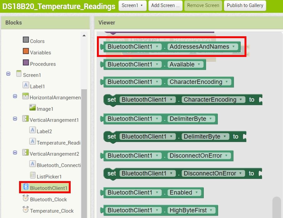
Add Bluetooth Client and Clocks to MIT App Inventor
Go to Palette > Connectivity and click and drag BluetoothClient in the viewer. This is a non-visible component of our app and will let us connect it with our Bluetooth module.

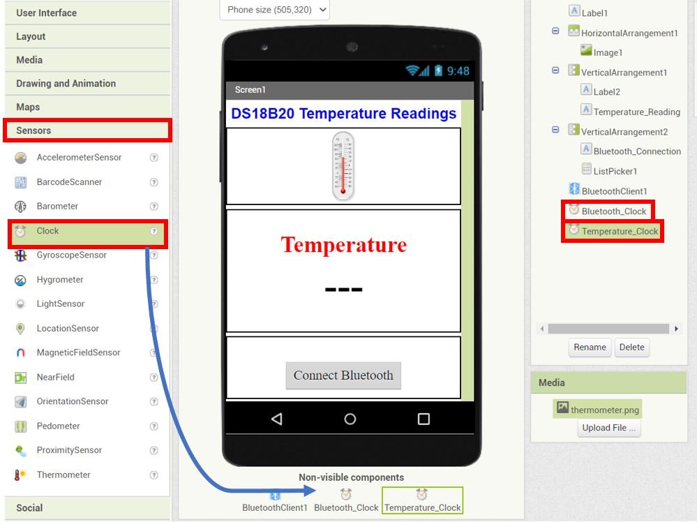
Next head over to Palette > Sensors and drag and drop two clocks in the viewer. Rename one clock as ‘Bluetooth_Clock’ and the other one as ‘Temperature_Clock.’ These are also non-visible components of the app used for monitoring the time.
Blocks Layout
Now click on the ‘Blocks’ button found at the top of the window. A new editor will open up. Here we will design how our app will respond. We will assemble blocks in the workspace by clicking and dragging them.

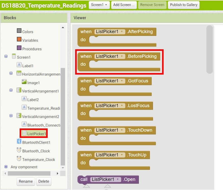
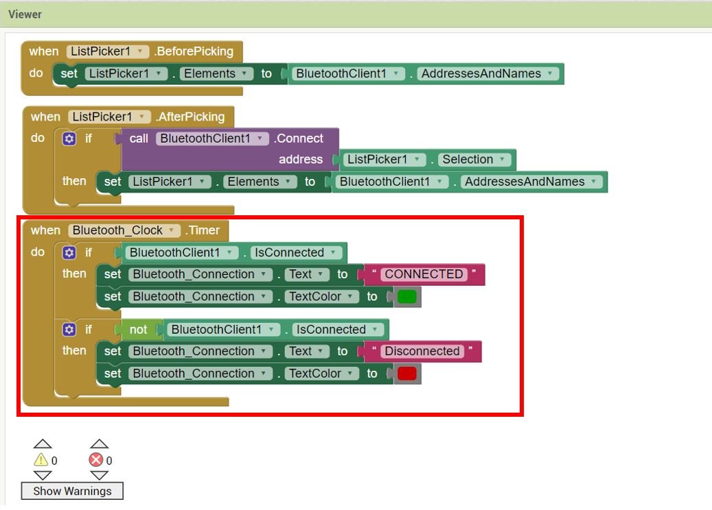
First, click ‘ListPicker1’ and a series of blocks will open. Click and drag the ‘BeforePicking’ block in the workspace.
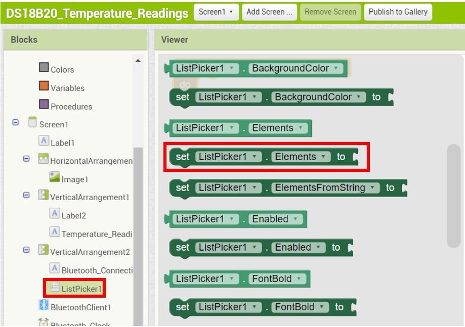
Likewise, select the set Elements to block shown below:
From BluetoothClient1, click and drag AddressesAndNames as shown below:
Place these three blocks in the workspace as shown below:

The blocks fit like puzzle pieces. Now similarly follow the diagram below and arrange all the blocks for the List Picker. The if-then block is found in Built-in > Control.

Go to Bluetooth_Clock and select the block shown below:

Assemble the blocks for the Bluetooth_Clock as shown below:
Next, inside the Blocks section, go to Built-in > Variables and select the initialize global name to block. Click and drag it to the viewer.

Here we are initializing the global variable ‘temperatureReading’ to store the temperature values. Initially it holds the value 0. This temperatureReading will later hold the value received from the Bluetooth module after a successful Bluetooth connection has been established between the android phone and the module.

Lastly, assemble the blocks for the Temperature_Clock as shown below:

Here the Temperature_Reading label’s text will be set to the value that is received by the sensor.
For more information regarding building your app in MIT App Inventor, follow this guide: App Inventor Tutorials.
Setting up App Inventor on Smartphone
Now, as we have built our app in MIT app inventor and have also written its code let’s move ahead and install the App Inventor in our smartphone. Through this, we will be able to access our app on our smartphone from anywhere around the world. Follow the steps closely.
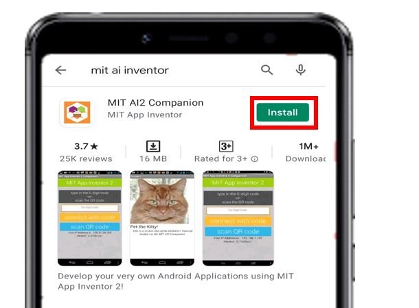
Firstly, go to Play Store and install ‘MIT AI2 Companion.’
After you installed the application, open it. You will have to either scan a QR code or type a 6-character code.
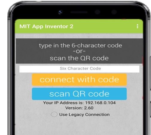
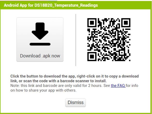
To access these, go to MIT App Inventor main page where we initially built our app. Go to Build > Android App (.apk). After a few moments your barcode will get generated. You can either download the .apk file or scan the barcode using the MIT App Inventor.
After installing the .apk file on our android phone, we will be able to view the screen which we created.
Now, we will demonstrate the sensor readings.
Demonstration
Choose the correct board and COM port before uploading your code to the board.
Go to Tools > Board and select Arduino Module.

Next, go to Tools > Port and select the appropriate port through which your board is connected.
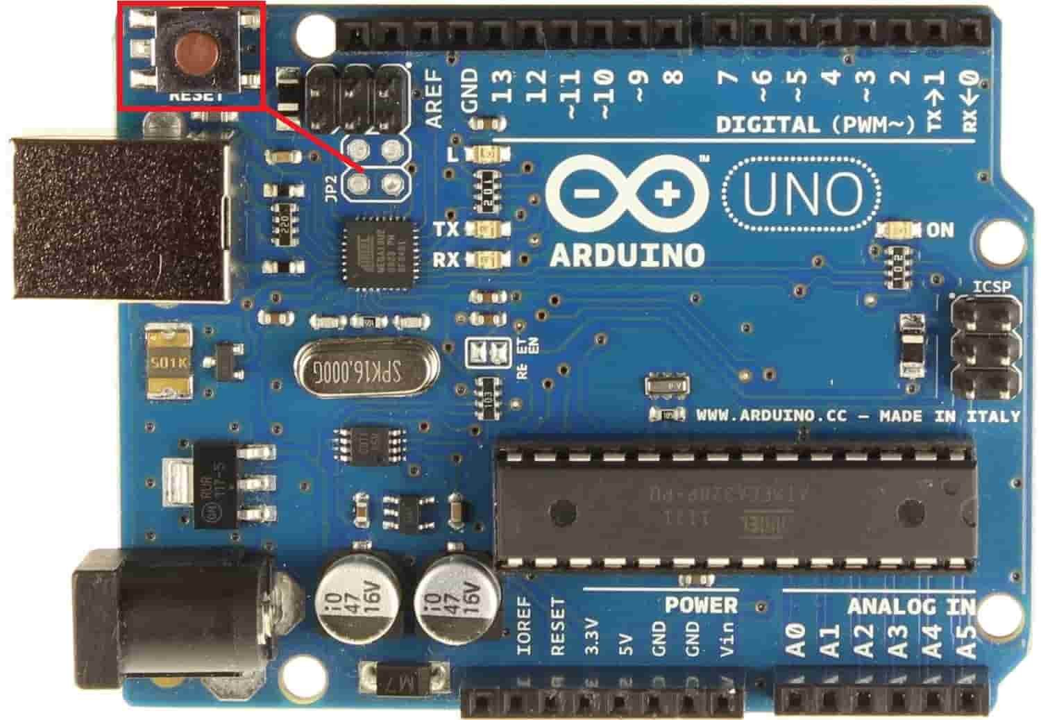
Click on the upload button to upload the code into the Arduino development board. After you have uploaded your code to the Arduino development board press its ENABLE button.
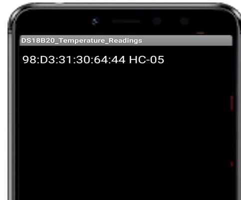
Open the MIT Companion app on your smartphone. Pair your android phone with HC-05 module. Now press the ‘Connect Bluetooth’ button.
Select HC-05 Bluetooth module to connect with.
After a few moments, the temperature reading displays on the screen. After every 5 seconds, it gets updated.


Video demo:
You may also like to read:
- Arduino Send Messages from Android to LCD with MIT App Inventor
- Control ESP32 over Internet using Android App with MIT App Inventor
- Arduino RGB LED Control using Android App with MIT App Inventor
- ESP8266 Send Sensor Readings to Google Firebase Database and Create Web App
- ESP32 Send Sensor Readings to Google Firebase and Display on Android app
- Control ESP32 Outputs using Blynk App and Arduino IDE
- IoT CCTV Camera using ESP32 CAM & Blynk App – Live Streaming
- Control ESP8266 Outputs using Blynk App and Arduino IDE
Hi Guys
I am looking to use a esp32 to monitor a mpu 6050 for a tilt sensor in my caravan
I would like to have this connect via bluetooth.
Any way I can modify this scetch to use the esp32 instead of the uno? and which libarery would you install for the mpu 6050
Cheers
Dave
Thank you very much for this excellent tutorial. Since the legacy Blynk software no longer works, I had to figure out a way to build my own Smartphone App and have it communicate with an Arduino. With the help of this tutorial I was able to do this in less than four hours. Incredible!
non-visible component (Bluetooth client1,bluetooth_clock, Temperature_Clock) is not showing in the designer. I have to change its properties. Please help me what to do.
hi, can you do tutorial on how to display multiple ir sensor. and each sensor update the label on mit app inventor. example parking slot if slot 1 have been parked the sensor send data to the apps and update the label text saying slot 1 has been parked. and if slot 2 have not been park the label text saying slot available. Thank you.